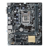
ASUS H110M-K X
1-3
Intel
®
H110 Serial ATA 6.0Gb/s connectors (7-pin SATA6G_1~4)
TheseconnectorsconnecttoSerialATA6.0Gb/sharddiskdrivesviaSerialATA
6.0Gb/ssignalcables.
Whenusinghot-plugandNCQ,settheSATA Mode SelectionitemintheBIOSto
[AHCI].
USB 3.0 connectors (20-1 pin USB3_12)
ConnectaUSB3.0moduletoanyoftheseconnectorsforadditionalUSB3.0
frontorrearpanelports.ThisconnectorcomplieswithUSB3.0specicationsand
providesfasterdatatransferspeedsofupto5Gbps,fasterchargingtimeforUSB-
chargeabledevices,optimizedpowerefciency,andbackwardcompatibilitywith
USB2.0.
Clear RTC RAM (2-pin CLRTC)
ThisheaderallowsyoutocleartheCMOSRTCRAMdataofthesystemsetup
informationsuchasdate,time,andsystempasswords.
To erase the RTC RAM:
1. TurnOFFthecomputerandunplugthepowercord.
2. Useametalobjectsuchasascrewdrivertoshortthetwopins.
3. PlugthepowercordandturnONthecomputer.
4. Holddownthe<Del>keyduringthebootprocessandenterBIOSsetupto
re-enterdata.
Ifthestepsabovedonothelp,removetheonboardbatteryandshortthe
twopinsagaintocleartheCMOSRTCRAMdata.AfterclearingtheCMOS,
reinstallthebattery.
USB 2.0 connector (10-1 pin USB910)
ConnecttheUSBmodulecabletoanyoftheseconnectors,theninstallthemodule
toaslotopeningatthebackofthesystemchassis.ThisUSBconnectorcomplies
withUSB2.0specicationsandsupportsupto480Mbpsconnectionspeed.
Digital audio connector (4-1 pin SPDIF_OUT)
ConnecttheS/PDIFOutmodulecabletothisconnector,then
installthemoduletoaslotopeningatthebackofthesystem
chassis.
TPM connector (14-1 pin TPM)
ConnectaTrustedPlatformModule(TPM)systemtothisconnectortoenhance
networksecurity,protectdigitalidentities,andensureplatformintegrity.
CLRTC
+3V_BAT
GND
PIN 1
SPDIF_OUT
+5V
SPDIFOUT
GND
PIN 1
TPM
+3VSB
S_PCIRST#_TBD
GND
C_PCICLK_TPM
+3V
+3V
F_CLKRUN
F_SERIRQ
F_FRAME#
F_LAD3
F_LAD2
F_LAD1
F_LAD0

 Loading...