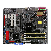
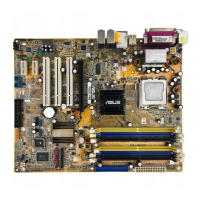
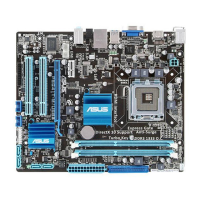
ASUS P5GD2 PremiumASUS P5GD2 Premium
ASUS P5GD2 PremiumASUS P5GD2 Premium
ASUS P5GD2 Premium
2-312-31
2-312-31
2-31
10.10.
10.10.
10.
Optical drive audio connector (4-pin CD)Optical drive audio connector (4-pin CD)
Optical drive audio connector (4-pin CD)Optical drive audio connector (4-pin CD)
Optical drive audio connector (4-pin CD)
This connector is for the 4-pin audio cable that connects to the audio
connector at the back of the optical drive.
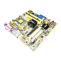
P5GD2 Premium
P5GD2 Premium
P5GD2 Premium ATX Power Connectors
EATXPWR1ATX12V1
GND
+12V DC
GND
+12V DC
+3 Volts
+3 Volts
Ground
+5 Volts
+5 Volts
Ground
Ground
Power OK
+5V Standby
+12 Volts
-5 Volts
+5 Volts
+3 Volts
-12 Volts
Ground
Ground
Ground
PSON#
Ground
+5 Volts
+12 Volts
+3 Volts
+5 Volts
Ground
P5GD2 Premium CD audio connector
CD
Right Audio Channel
Left Audio Channel
Ground
Ground
11.11.
11.11.
11.
GAME/MIDI port connector (16-1 pin GAME1)GAME/MIDI port connector (16-1 pin GAME1)
GAME/MIDI port connector (16-1 pin GAME1)GAME/MIDI port connector (16-1 pin GAME1)
GAME/MIDI port connector (16-1 pin GAME1)
This connector is for a GAME/MIDI port. Connect the USB/GAME
module cable to this connector, then install the module to a slot
opening at the back of the system chassis. The GAME/MIDI port
connects a joystick or game pad for playing games, and MIDI devices
for playing or editing audio files.
P5GD2 Premium
®
P5GD2 Premium Game connector
GAME1
+5V +5V
J2B1
J2CX
MIDI_OUT
J2CY
J2B2
MIDI_IN
J1B1
J1CX
GND
GND
J1CY
J1B2
+5V
 Loading...