1-28 Chapter 1: Product introduction
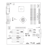
P5P800-VM IDE connectors
NOTE: Orient the red marking
(usually zigzag) on the IDE
ribbon cable to PIN 1.
SEC_IDE
PRI_IDE
PIN 1 PIN 1
P5P800-VM
• Pin 20 on the IDE connector is removed to match the covered hole
on the Ultra DMA cable connector. This prevents incorrect insertion
when you connect the IDE cable.
• Use the 80-conductor IDE cable for Ultra DMA 100/66/33 IDE
devices.
2. IDE connectors (40-1 pin PRI_IDE, SEC_IDE)
These connectors are for Ultra DMA 100/66 signal cables. There
are three interfaces on each Ultra DMA 100/66 signal cables: blue,
black, and gray. Connect the blue interface into the motherboadʼs IDE
connector, then select the following modes to congure your hard
disk drive(s).
Single device Cable-select or Master - Black
Two devices Cable-select Master Black
Slave Gray
Master Master Black or gray
Slave Slave
Drive Jumper Setting Mode of Devices Cable Connector
If any device jumper is set to “Cable-select”, make sure all other device
jumpers have the same setting.
 Loading...