ASUS P5P800-VM 1-31
8. Front panel audio connector (10-1 pin FP_AUDIO)
This connector is for a chassis-mounted front panel audio I/O module
that supports legacy AC ‘97 audio standard. Connect one end of the
front panel audio I/O module cable to this connector.
P5P800-VM Front panel audio connector
FP_AUDIO
BLINE_OUT_
L
MIC2
Line out_R
Line out_L
BLINE_OUT_
R
NC
MICPWR
+5V
A
AGND
P5P800-VM
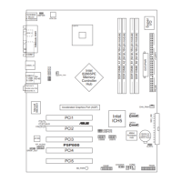
7. ATX power connectors (20-pin ATXPWR,4-pin ATX12V)
These connectors are for an ATX power supply. The plugs from
the power supply are designed to t these connectors in only one
orientation. Find the proper orientation and push down rmly until the
connectors completely t.
•
Do not forget to connect the 4-pin ATX +12 V power plug;
otherwise, the system will not boot up.
• Use a PSU with a minimum power rating of 300 W on this
motherboard. Use of a PSU with a higher power output
is recommended when conguring a system with more
power-consuming devices. The system may become unstable or may
not boot up if the power is inadequate.
P5P800-VM ATX power connector
ATXPWRATX12V
+12V DC GND
+12V DC GND
+3.3VDC
-12.0VDC
GND
PS_ON#
GND
GND
GND
-5.0VDC
+5.0VDC
+5.0VDC
PWR_OK
+12.0VDC
+3.3VDC
+3.3VDC
GND
+5.0VDC
GND
+5.0VDC
GND
+5VSB
P5P800-VM
 Loading...