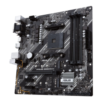
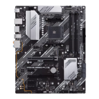
PRIME B550M-K ARGB
1-5
DO NOT short-circuit the pins except when clearing the RTC RAM. Short-circuiting or
placing a jumper cap will cause system boot failure!
If the steps above do not help, remove the onboard button cell battery and short the two
pins again to clear the CMOS RTC RAM data. After clearing the CMOS, reinstall the button
cell battery.
13. COM Port header
The COM (Serial) Port header allows you to connect a COM port module.
Connect the COM port module cable to this header, then install the module to
a slot opening on the system chassis.
The COM port module is purchased separately.
14. Front Panel Audio header
The Front Panel Audio header is for a chassis-mounted front panel audio I/O
module that supports HD Audio. Connect one end of the front panel audio I/O
module cable to this header.
We recommend that you connect a high-denition front panel audio
module to this header to avail of the motherboard’s high-denition audio
capability.
15. S/PDIF Out header
The S/PDIF Out header allows you to connect the Sony/Philips Digital
Interface (S/PDIF) Out module.
The S/PDIF module is purchased separately.
16. Speaker header
The 4-pin header is for the chassis-mounted system warning speaker. The
speaker allows you to hear system beeps and warnings.
17. SPI TPM header
This header supports a Trusted Platform Module (TPM)
system with a Serial Peripheral Interface (SPI), allowing you to
securely store keys, digital certicates, passwords, and data.
A TPM system also helps enhance network security, protects
digital identities, and ensures platform integrity.
The TPM module is purchased separately.
PIN 1
RXD
DTR
DSR
CTS
COM
DCD
TXD
GND
RTS
RI
AAFP
AGND
NC
SENSE1_RETUR
SENSE2_RETUR
PORT1 L
PORT1 R
PORT2 R
SENSE_SEND
PORT2 L
HD-audio-compliant
pin definition
+5V
GND
GND
Speaker Out
SPEAKER
PIN 1
TPM
PIN 1
SPI_TPM_PWR
SPI_TPM_RST#
NC
SPI_PWR
SPI_CS0#_R
SPI_MISO
SPI_HOLD#_R
SPI_TPM_IRQ#
SPI_TPM_CS#
SPI_BIOS_WP#
GND
SPI_CLK
SPI_MOSI
 Loading...