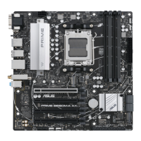
ASUS PRIME B650-PLUS WIFI
1-3
6. M.2 Slots (Key M)
The M.2 slots allow you to install M.2 devices such as M.2 SSD modules.
For AMD Ryzen™ 9000 & 7000 Series Desktop Processors:
M.2_1 slot (Key M), type 2242/2260/2280/22110 (supports PCIe 5.0 x4 mode)
M.2_2 slot (Key M), type 2242/2260/2280/22110 (supports PCIe 4.0 x4 mode)
For AMD Ryzen™ 8000 Series Desktop Processors:
M.2_1 slot (Key M), type 2242/2260/2280/22110 (supports PCIe 4.0 x4 mode)
M.2_2 slot (Key M), type 2242/2260/2280/22110 (supports PCIe 4.0 x4/x2 mode)
7. SATA 6Gb/s ports
The SATA 6Gb/s ports allow you to connect SATA devices such as optical disc drives and
hard disk drives via a SATA cable.
8. USB 5Gbps Type-C
®
Front Panel connector
The USB 5Gbps Type-C
®
connector allows you to connect a USB
5Gbps module for an additional USB 5Gbps Type-C
®
port. The
connector provides a data transfer speed of up to 5 Gb/s.
The USB 5Gbps Type-C
®
module is purchased separately.
9. USB 5Gbps header
The USB 5Gbps header allows you to connect a USB 5Gbps module
for additional USB 5Gbps ports. The USB 5Gbps header provides
data transfer speeds of up to 5 Gb/s.
The USB 5Gbps module is purchased separately.
10. USB 2.0 headers
The USB 2.0 headers allow you to connect USB modules for additional USB
2.0 ports. The USB 2.0 headers provide data transfer speeds of up to 480
Mb/s.
DO NOT connect a 1394 cable to the USB connectors. Doing so will
damage the motherboard!
The USB 2.0 module is purchased separately.
11. Addressable Gen 2 headers
The Addressable Gen 2 headers allow you to connect individually
addressable RGB WS2812B LED strips or WS2812B based LED strips.
The Addressable Gen 2 header supports WS2812B addressable RGB
LED strips (5V/Data/Ground), with a maximum power rating of 3A (5V),
and the addressable headers on this board can handle a combined
maximum of 500 LEDs.
NC
CC1
VBUS
RX1-
RX1+
GND
TX1-
TX1+
TX2+
TX2-
GND
RX2+
RX2-
GND
D-
D+
USB3+5V
IntA_P1_SSRX-
IntA_P1_SSRX+
GND
IntA_P1_SSTX-
IntA_P1_SSTX+
GND
IntA_P1_D-
IntA_P1_D+
GND
PIN 1
USB3+5V
IntA_P2_SSRX-
IntA_P2_SSRX+
GND
IntA_P2_SSTX-
IntA_P2_SSTX+
GND
IntA_P2_D-
IntA_P2_D+
USB+5V
USB_P1-
USB_P1+
GND
NC
USB+5V
USB_P2-
USB_P2+
GND
PIN 1
ADD_GEN 2
+5V
Data
Ground
PIN 1

 Loading...