1-3
3. Expansion slots
This motherboard supports one PCIe x16 graphics card and one PCIe x1 network card, SCSI
card or other cards that comply with the PCI Express specification.
4. Fan headers
The Fan headers allow you to connect fans to cool the system.
5. Power connectors
These Power connectors allow you to connect your motherboard to a power supply. The
power supply plugs are designed to fit in only one orientation. Find the proper orientation and
push down firmly until the power supply plugs are fully inserted.
Ensure to connect the 8-pin power plug.
We recommend that you use a PSU with a higher power output when configuring a system
with more power-consuming devices. The system may become unstable or may not boot
up if the power is inadequate.
6. M.2 slot (Key M)
The M.2 slot allows you to install an M.2 device such as an M.2 SSD module.
Intel
®
H610 Chipset
- M.2 slot (Key M), type 2242/2260/2280 (supports PCIe 3.0 x4 mode)
The M.2 SSD module is purchased separately.
7. SATA 6Gb/s ports
The SATA 6Gb/s ports allow you to connect SATA devices such as optical disc drives and
hard disk drives via SATA cables.
8. USB 3.2 Gen 1 header
The USB 3.2 Gen 1 header allows you to connect a USB 3.2 Gen
1 module for additional USB 3.2 Gen 1 ports. The USB 3.2 Gen 1
header provides data transfer speeds of up to 5 Gb/s.
The USB 3.2 Gen 1 module is purchased separately.
9. USB 2.0 header
The USB 2.0 header allows you to connect a USB module for an additional
USB 2.0 port. The USB 2.0 header provides data transfer speeds of up to 480
Mb/s.
DO NOT connect a 1394 cable to the USB connectors. Doing so will damage the
motherboard!
The USB 2.0 module is purchased separately.
FAN PWM
FAN IN
FAN PWR
GND
FAN PWM
FAN IN
FAN PWR
GND
GND
FAN PWR
FAN IN
FAN PWM
USB3+5V
IntA_P1_SSRX-
IntA_P1_SSRX+
GND
IntA_P1_SSTX-
IntA_P1_SSTX+
GND
IntA_P1_D-
IntA_P1_D+
GND
USB3+5V
IntA_P2_SSRX-
IntA_P2_SSRX+
GND
IntA_P2_SSTX-
IntA_P2_SSTX+
GND
IntA_P2_D-
IntA_P2_D+
PIN 1
USB+5V
USB_P11-
USB_P11+
GND
NC
USB+5V
USB_P14-
USB_P14+
GND
+5V DC
Data(negative)
Data(positive)
Groud
PIN 1
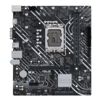
PRIME H610M-K ARGB
 Loading...