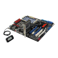
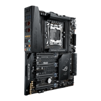
2.2.2 Layout-Inhalt
Weitere Informationen zu den internen und Rücktafel -Anschlüssen nden Sie
in Abschnitt 2.9 Anschlüsse.
Anschlüsse/Jumper/Schalter/Steckplätze Seite
1. ATX-Netzanschlüsse
(24-pol. EATXPWR, 8-pol. EATX12V, 4-pol. EZ_PLUG1—2)
2-45
2.
Temperatursensorkabelanschlüsse (2-pol. OPT_TEMP1–3) 2-43
3. CPU-, Gehäuse- und optionale Lüfteranschlüsse (4-pol. CPU_FAN;
4-pol. PWR_FAN; 4-pol. CHA_FAN1–3; 4-pol. OPT_FAN1–3)
2-42
4.
LGA1366 CPU-Sockel 2-9
5. DDR3 DIMM-Steckplätze
2-14
6. LN2 Mode-Jumper (3-pol. LN2)
2-31
7. Einschalttaste
2-48
8. Reset-Taste
2-48
9. Q Reset-Taste
2-50
10. QPI_LL (3-pol. QPI_LL_SW)
2-31
11. GO-Taste
2-49
12. Marvell
®
Serial ATA 6.0 Gb/s-Anschlüsse (7-pol. SATA_6G_1/2 [rot]) 2-39
13. ICH10R Serial ATA-Anschlüsse (7-pol. SATA 1-6 [grau])
2-38
14. RTC RAM löschen (3-pol. CLRTC_SW)
2-30
15. BIOS-Schalter
2-49
16.
Systemtafelanschluss (20-8 pol. PANEL) 2-46
17. USB-Anschlüsse (10-1 pol. USB78, USB910, USB11)
2-40
18. OC Station-Anschluss (8-pol. OC_STATION)
2-40
19. IEEE 1394a-Anschluss (10-1 pol. IE1394_2)
2-41
20.
Digitaler Audioanschluss (4-1 pol. SPDIF_OUT) 2-43
21.
Fronttafelaudioanschluss (10-1 pol. AAFP) 2-44
ROG Rampage III Formula 2-7
 Loading...