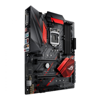
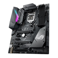
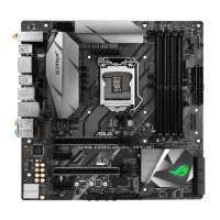
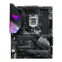
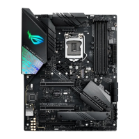
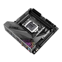
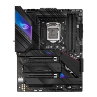
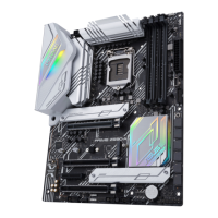
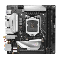
ASUS ROG STRIX Z370-I GAMING
1-3
Chapter 1
Refer to 1.1.8 Internal connectors and 2.2.1 Rear I/O connection for more information
about rear panel connectors and internal connectors.
Layout contents
Connectors/Jumpers/Buttons and switches/Slots Page
1. USB 3.1 Gen2 connector (U31G2_EC1) 1-12
2. CPU, AIO, and chassis fan connectors (4-pin CPU_FAN; 4-pin AIO_
PUMP; 4-pin CHA_FAN)
1-14
3. ATX power connectors (24-pin EATXPWR; 8-pin EATX12V) 1-15
4. Thermal sensor cable connector (2-pin T_SENSOR) 1-18
5. LGA1151 CPU socket 1-4
6. M.2 sockets (M.2_1; M.2_2) 1-17
7. DDR4 DIMM slots 1-5
8. POST State LEDs 1-10
9. RGB LED 1-10
10. Addressable RGB header (4-1 pin ADD_HEADER) 1-18
11. System panel connector (10-1 pin PANEL) 1-16
12. Speaker connector (4-pin SPEAKER) 1-13
13. Intel
®
Serial ATA 6 Gb/s connectors (7-pin SATA6G_12, SATA 6G_34) 1-11
14. USB 3.1 Gen1 connector (20-1 pin U31G1_12)
1-12
15. Clear RTC RAM jumper (2-pin CLRTC) 1-8
16. USB 2.0 connector (10-1 pin USB1112) 1-13
17. Front panel audio connector (10-1 pin AAFP) 1-11
18. RTC Battery header (2-pin BATT_CON) 1-9
 Loading...

