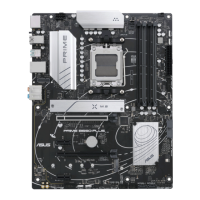
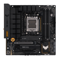
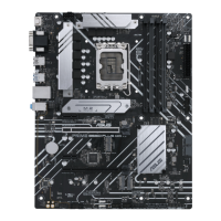
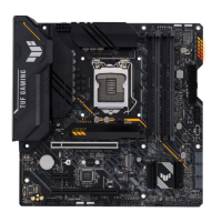
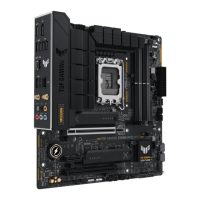
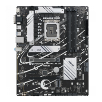
1-4
6. M.2 slots (Key M)
The M.2 slots allow you to install M.2 devices such as M.2 SSD modules.
• AMD Ryzen™ 7000 Series Desktop Processors:
- M.2_1 slot supports PCIe 5.0 x4 mode M Key design and type 2242/2260/2280
storage devices.
- M.2_2 slot supports PCIe 4.0 x4 mode M key design and type 2242/2260/2280
storage devices.
• AMD B650 Chipset:
- M.2_3 slot supports PCIe 4.0 x4 mode M key design and type
2242/2260/2280/22110 storage devices.
The M.2 SSD module is purchased separately.
7. SATA 6Gb/s ports
The SATA 6Gb/s ports allow you to connect SATA devices such as optical disc drives and
hard disk drives via SATA cables.
8. USB 20Gbps Type-C
®
Front Panel connector
The USB 20Gbps Type-C
®
connector allows you to connect a USB
20Gbps Type-C
®
module for additional USB 20Gbps ports on the front
panel. The USB 20Gbps Type-C
®
connector provides data transfer
speeds of up to 20 Gb/s.
The USB 20Gbps Type-C
®
module is purchased separately.
9. USB 5Gbps header
The USB 5Gbps header allows you to connect a USB 5Gbps
module for additional USB 5Gbps ports. The USB 5Gbps header
provides data transfer speeds of up to 5 Gb/s.
The USB 5Gbps module is purchased separately.
10. USB 2.0 headers
The USB 2.0 headers allow you to connect a USB module for additional USB
2.0 ports. The USB 2.0 headers provide data transfer speeds of up to 480
Mb/s.
DO NOT connect a 1394 cable to the USB connectors. Doing so will
damage the motherboard!
The USB 2.0 module is purchased separately.
11. Addressable Gen 2 headers
The Addressable Gen 2 headers allow you to connect individually addressable
RGB WS2812B LED strips or WS2812B based LED strips.
The Addressable Gen 2 headers support WS2812B addressable RGB LED strips (5V/Data/
Ground), with a maximum power rating of 3A (5V), and the addressable headers on this
board can handle a combined maximum of 500 LEDs.
SBU2
SBU1
CC1
VBUS
RX1-
RX1+
GND
TX1-
TX1+
VBUS
VBUS
TX2+
TX2-
GND
RX2+
RX2-
GND
D-
D+
CC2
USB3+5V
IntA_P1_SSRX-
IntA_P1_SSRX+
GND
IntA_P1_SSTX-
IntA_P1_SSTX+
GND
IntA_P1_D-
IntA_P1_D+
GND
PIN 1
USB3+5V
IntA_P2_SSRX-
IntA_P2_SSRX+
GND
IntA_P2_SSTX-
IntA_P2_SSTX+
GND
IntA_P2_D-
IntA_P2_D+
USB+5V
USB_E1-
USB_E1+
GND
NC
USB+5V
USB_E2-
USB_E2+
GND
PIN 1
ADD_GEN 2
+5V
Data
Ground
PIN 1
Chapter 1: Product Introduction
 Loading...
