1-4
Chapter 1: Product introduction
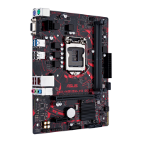
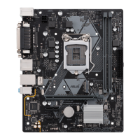
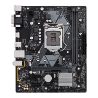
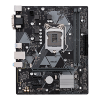
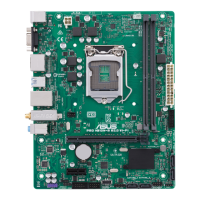
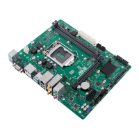
Serial port connector (10-1 pin COM)
Connect the serial port module cable to this connector, then install the module to a
slot opening at the back of the system chassis.
Front panel audio connector (10-1 pin AAFP)
This connector is for a chassis-mounted front panel audio I/O module that supports
HD Audio standard. Connect one end of the front panel audio I/O module cable to
this connector.
• We recommend that you connect a high-denition front panel audio module to this
connector to avail of the motherboard’s high-denition audio capability.
• If you want to connect a high-denition front panel audio module to this connector,
set the Front Panel Type item in the BIOS setup to [HD Audio]. By default, this
connector is set to [HD Audio].
PCI Express 2.0 x1 slots
This motherboard has two PCI Express 2.0 x1 slots that support PCI Express x1
network cards, SCSI cards, and other cards that comply with the PCI Express
specications.
PCI Express 3.0/2.0 x16 slot
This motherboard has a PCI Express 3.0/2.0 x16 slot that supports PCI Express
3.0/2.0 x16 graphic cards complying with the PCI Express specications.
M.2 socket 3
These sockets allow you to install M.2 (NGFF) SSD
modules.
M.2(SOCKET3)
When using PCI cards on shared slots, ensure that the
drivers support “Share IRQ” or that the cards do not need
IRQ assignments. Otherwise, conicts will arise between the
two PCI groups, making the system unstable and the card
inoperable.
• These M.2 sockets support M Key and 2242/2260/2280 storage devices.
•
When a device in SATA mode is installed on the M.2 socket, the SATA_2
port cannot be used.

 Loading...