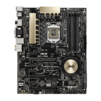
ASUS Z97-PRO Series
1-5
Chapter 1
Layout contents
Connectors/Jumpers/Buttons and switches/Slots Page
1. ATX power connectors (24-pin EATXPWR, 8-pin EATX12V) 1-39
2. LGA1150 CPU socket 1-6
3. CPU, CPU optional, and chassis fan connectors (4-pin CPU_FAN,
4-pin CPU_OPT, 4-pin CHA_FAN1-4 )
1-38
4. DDR3 DIMM slots 1-7
5. CPU Over Voltage jumper (3-pin CPU_OV) 1-25
6. MemOK! button 1-21
7. EZ XMP switch 1-20
8. USB 3.0 connectors (20-1 pin USB3_12, USB3_34) 1-36
9. EPU switch 1-23
10. Intel
®
Z97 Serial ATA 6 Gb/s connectors (7-pin SATA6G_12, SATA6G_34,
SATA6G_56/ SATAEXPRESS)
1-33
11. ASMedia
®
Serial ATA 6 Gb/s connectors (7-pin SATA6G_E12) 1-34
12. M.2 Socket 3 1-34
13. T_Sensor connector (2-pin T_SENSOR1) 1-42
14. DirectKey connector (2-pin DRCT) 1-41
15. System panel connector (20-8 pin PANEL) 1-40
16. Clear RTC RAM (3-pin CLRTC) 1-24
17. USB 2.0 connectors (10-1 pin USB1112; USB1314) 1-37
18. TPU switch 1-22
19. TPM connector (20-1 pin TPM) 1-41
20. BIOS Flashback button 2-12
21. Power-on button 1-20
22. Thunderbolt header (5-pin TB_HEADER) 1-42
23. Front panel audio connector (10-1 pin AAFP) 1-35
24. Digital audio connector (4-1 pin SPDIF_OUT) 1-35
25. Q-Code LEDs 1-28
 Loading...