M-23
Providing Solutions to the HVAC Industry ATI80 - 10/23 © Aire Technologies
Air Control Damper
Aire Technologies 1502 Industrial Drive, Monongahela, PA 15063 1-866-421-AIRE AireTechnologies.com
INSTALLATION INSTRUCTIONS
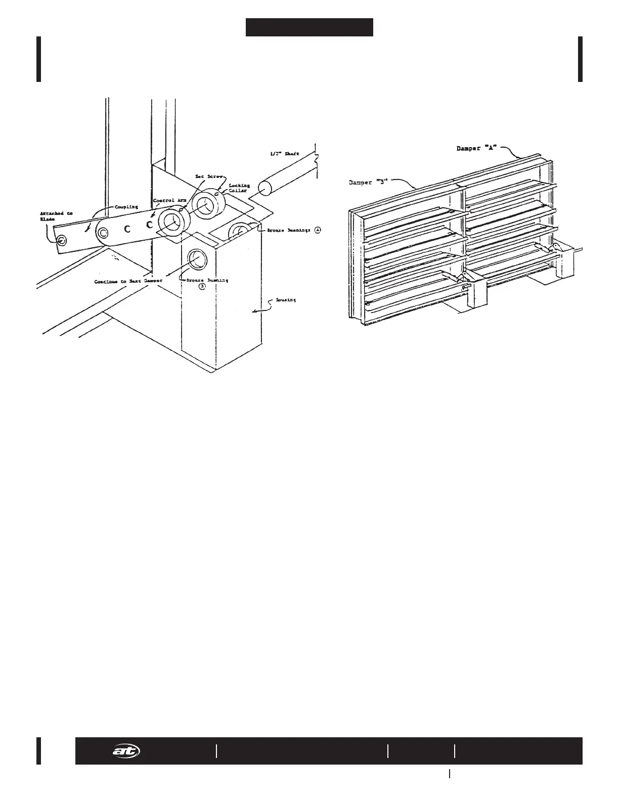
Installation of Jack Shaft Assembly for Multi Section Air Control Dampers
These dampers have been pre-assembled and tested before shipping. Please read instructions before beginning.
1. Place dampers in order: A, B, C, etc. Make sure when facing side of damper with housing on it, the housing is on the right hand side of the damper.
2. Use the self-tapping screws supplied to attach the frames together through the pre-drilled holes.
3. Bring with damper “A”.
4. Place the ½” rod halfway through bronze bushing.
5. Slide the locking collar (should be wired to control arm for shipping) over the shaft.
6. Next, hold the control arm up (which is attached to the bottom blade) and slide the ½” rod through it until he rod sticks out of bronze bushing (B).
7. Continue sliding the rod to damper “B”.
8. Repeat steps 4, 6, and 7 until the rod has attached all single section dampers. (Note: only damper “A” will have a locking collar.)
9. Once the ½” rod is in place, close damper “A”. The control arm and coupling should now be in a straight line.
10. Tighten the set screw of the control arm with a 1/8” Allen wrench.
11. Slide the locking collar over to the opposite side (away from control arm) of the housing and tighten its set screw. This should allow little side to side
movement of the ½” rod. If there is movement, this may cause added friction in opening the dampers.
12. Move to damper “B”. Shut damper and tighten set screw. Repeat this until all set screws are tightened.
13. Cycle damper using 1/2” rod to ensure nothing is binding.
14. ½” rod may be adjusted side to side to allow for proper installation of actuator/hand quadrant.
 Loading...