3
PREPARATION
Keep hands away from pinch and crush points
that are created while folding and unfolding!
!
Figure 2
To avoid personal injury and property damage:
WARNING
!
5HDGXQGHUVWDQGDQGIROORZDOOSULQWHGPDWHULDOVSURYLGHGZLWKDQGRQWKLVSURGXFWEHIRUHXVH
'RQRWH[FHHGUDWHGFDSDFLW\5DWHGFDSDFLW\LVOEVLQFOXGHVSHUVRQWRROVHTXLSPHQWSHUVRQDOLWHPV
6LWGRZQJHQWO\$YRLGVKRFNORDGVFDXVHGE\MXPSLQJRUIDOOLQJRQWRVHDW
'RQRWVWDQGRQVHDW
%HZDUHRISLQFKDQGFUXVKKD]DUGVZKHQIROGLQJDQGXQIROGLQJ
.HHSRXWRIWKHUHDFKRIFKLOGUHQ7KLVGHYLFHLVQRWDSSURSULDWHIRUFKLOGUHQ¶VXVH
8VHRQVPRRWKOHYHOVXUIDFHVRQO\
Keep hands away from pinch and crush points that are created during use! Be alert and sober when
XVLQJWKLVSURGXFW1HYHURSHUDWHWKLVHTXLSPHQWZKHQXQGHUWKHLQÀXHQFHRIGUXJVRUDOFRKRO
!
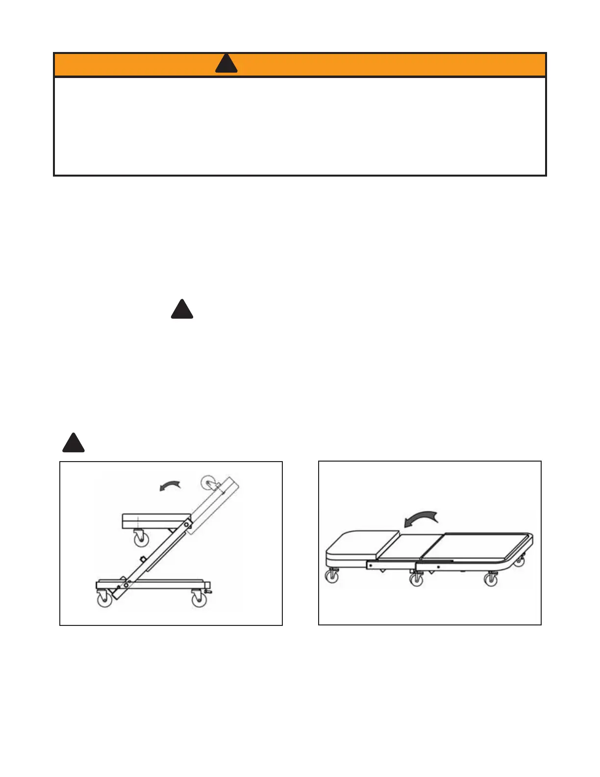
To transform creeper into seat position
Figure 3
To transform seat into creeper position
Step 1. Locate, then unlock the spring loaded Lock
Pin by pulling out until disengaged, at the same time
ÀLSWKH+HDG)UDPHDQG0LGGOH)UDPHXSZDUGDQG
back towards the Rear Frame section until the Lock
Pin can engage the Creeper Seat Locking Sleeve
)LJ(QVXUH/RFN3LQLVIXOO\HQJDJHG
6WHS)OLSWKH+HDG)UDPHIRUZDUGXQWLOKRUL]RQWDO
Step 3. Unlock the spring loaded Lock Pin by pull-
ing out until disengaged, then reverse steps 1, 2 to
convert Creeper Seat into Creeper.
8VHDVXLWDEOHRSHQHQGZUHQFKWRDWWDFKWKHKHDGIUDPHFDVWHUVWR+HDG)UDPH+DQGWLJKWHQZLWKRSHQHQG
wrench.
3. Use a 5 mm hex-key to attach the remaining casters to the Rear Frame. Insert the threaded fasteners from
above, the casters from below (as seen in Fig. 1), then hand tighten with hex key.
4. Attach Parts Tray to Rear Frame channel as seen below.
%HIRUHEHJLQQLQJDVVHPEO\RISURGXFWPDNHVXUHDOOSDUWVDUHSUHVHQW&RPSDUHSDUWVZLWKSDFNDJHFRQWHQWV
list and Figure 1 illustration. If any part is missing or damaged, do not attempt to assemble, install or operate the
product. Contact customer service for replacement parts.
Contents: 1 creeper body, 6 casters, 4 fasteners
Dimensions: 40” X 18” X 7-1/2”
ASSEMBLY INSTRUCTIONS (see Figure 1)
1. Carefully unfold the creeper as seen in Fig. 1.
OPERATING INSTRUCTIONS (Refer to Fig. 2, 3)
Little instruction is necessary for the safe and proper use if all warning information is understood and followed.
 Loading...