Flight and Operations Manual of ATEC 321 Faeta ultralight aircraft with Rotax 912 iS Sport
ATEC v.o.s. Libice nad Cidlinou, Czech Republic Page 35 of 56
too. One hole is drilled in the horizontal tail body and two holes are in the head of the screw. Finally,
cover the hole on upper side of the HT with a white plastic sticker (to avoid water intrusion).
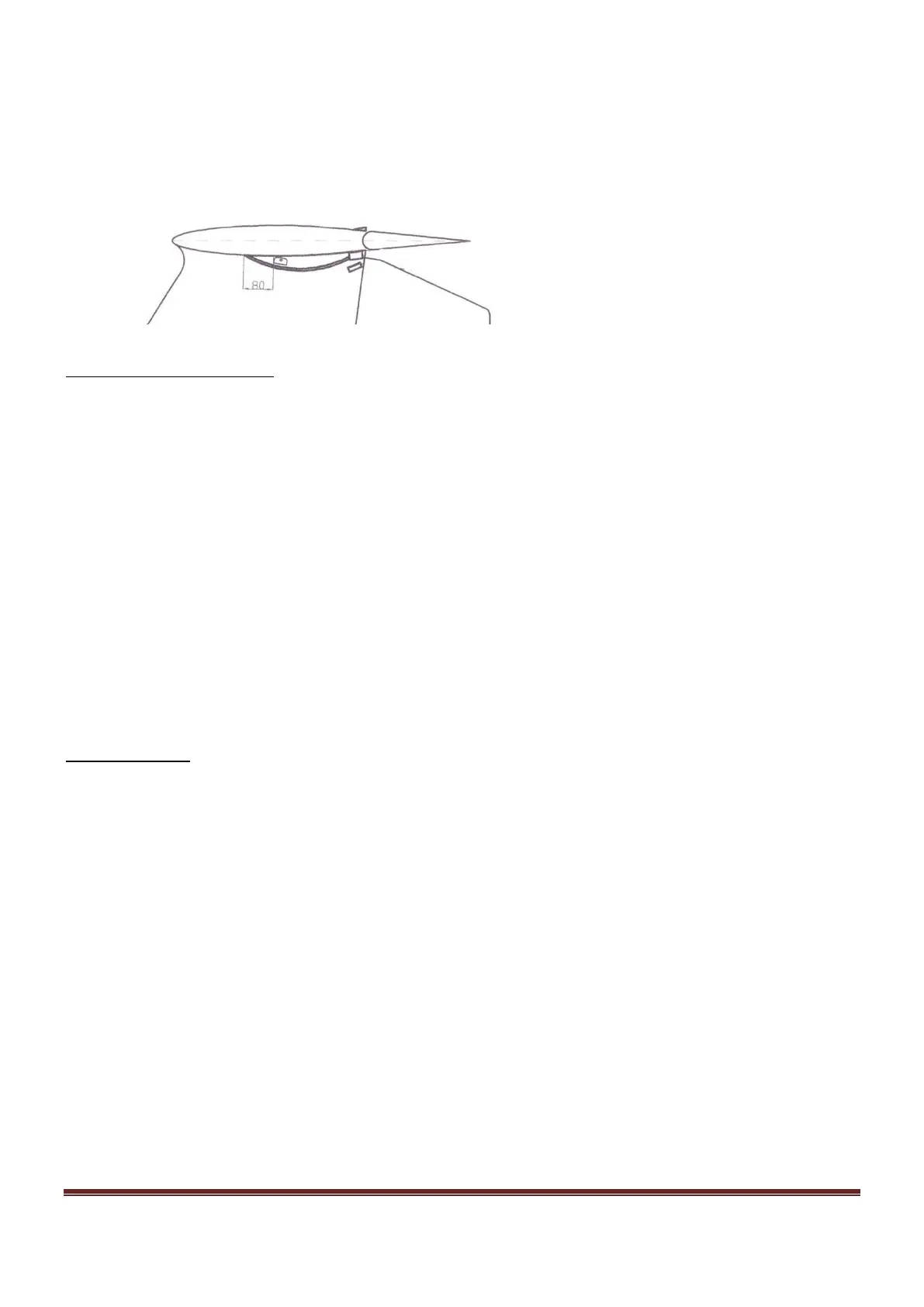
• Installation of the covers of the HT fittings
Covers of the HT fittings help to avoid vibration occurence in flight. Install the composite covers (with
double-side tape) according to following picture:
Horizontal tail disassembly
Remove the composite covers of the HT fittings. Pay attention not to damage them. These will be
needed for any next installation. Release and unscrew M6 screw (by which the position of HT is
adjusted) on the upper side of the HT. Release and remove M8 screws of the main HT fitting. Tilt the HT
so that it is possible to disconnect the pin of the HT pushrod. Remove the HT and secure the ball bearing
by a binding wire. Store the HT on a safe and dry place with stable temperature. The HT needs to be
enough secured and prevented from structural and surface damages.
6.3. Wings Assembly/Disassembly
At least two persons are needed for wings assembly/disassembly. One for assembly and one (or better
two) assistant(s) to hold and support the wing to avoid its fall and damage.
The assistant holds the wing by the wingtip and you hold it by the root (the third person can hold
the wing by the flap). Pick the wing up and then lay it down on any smooth, soft pad (e.g. mattress).
Wings assembly
(same for both left and right wing)
• Flap pushrod preparation - connection to the wing
Put the wing to the position by its leading edge down (on the soft pad). Hold the wing together with
your assistant, who deflects the flap so that the rod lever is protruding outside the wing. This enables
better access to connect the flap pushrod with the flap lever.
Pay attention to install the correct pushrod (LEFT („L“) or RIGHT („R“)) to appropriate wing. Pay
attention to correct pushrod position. Its non-adjustable end leads into the wing and the adjustable one
towards the fuselage. The sticker with letters L/R shall be situated on the upper side of the pushrod. Fix
the connection by the pin of Ø5mm and spacer + split pin (all such parts delivered with the pushrod).
• Aileron pushrod preparation - connection to the wing
Screw the aileron pushrod to the adjustable end protruding from the wing. Pay attention to install the
correct pushrod (LEFT or RIGHT) to appropriate aileron. Exact adjustment will be carried out later.
 Loading...