2920 1371 00
7
Instruction book Oil-free Air Division
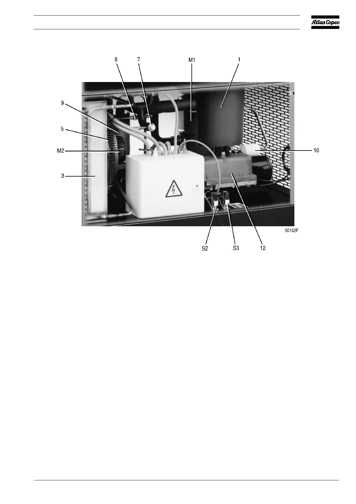
Fig. 4b. Side view of FD700
M1. Refrigerant compressor/motor
M2. Condenser cooling fan/motor
S2. High pressure shut-down switch
S3. Fan control switch
1. Condensate trap with automatic
discharge
2. Refrigerant shut-off valve
3. Condenser
4. Liquid refrigerant receiver
5. Fan
6. Sensor, high pressure shut-down
switch
7. Refrigerant expansion valve
8. Sight-glass with moisture indicator
9. Liquid separator
10. Refrigerant dryer
11. Sensor, fan control switch
12. Float valve
Figs. 4. Side views of air-cooled FD units
 Loading...