EN
www.atmos.cz
30-EN
Operation and maintenance manual - EN
23.
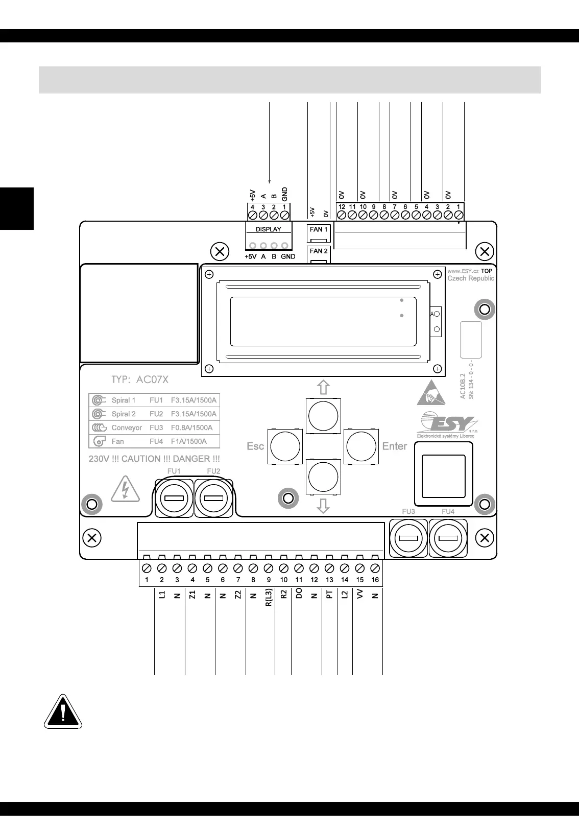
Connection diagram of AC07X electronic unit
CAUTION - For the connection of the TS, TV, TK and TSV sensors the connection of
individual wires is not decisive (can be interchanged). The TS, TV, TK and TSV sensors
are not part of the delivery, they must be purchased additionally within the set or separately,
Under the AC07X electronic control unit system there is a potentiometer for setting the
display contrast; however, we do not recommend you to change its setting.
external screen AC06B
fan speed transducer
sensor TSV
(water, waste gas)
input
input
input
input
input
sensor TK
(boiler)
sensor TV
sensor TS
photocell
power supply NTP (+12V) - special function
(water, top of the tank)
( , bottom of the tank)waste gas
input
not used
power supply
230V / 50Hz
2. ignitation spiral
[0.5 kW]
1. ignitation spiral
[0.5 kW]
[fuse on the boiler 6.3A/1500A]
shielding (TS, TV, TK, TSV)
[fusing by fuse on the boiler]
reserve with output
for burner connector
reserve number 2
special function
external conveyor
[fuse F0.8A1500A]
reserve number 2
special function
safety ther. of the burner
+ end limit switch
control thermostat of the boiler
burner fan
[fuse F1.0A1500A]
 Loading...