EN
www.atmos.cz
6-EN
Operation and maintenance manual - EN
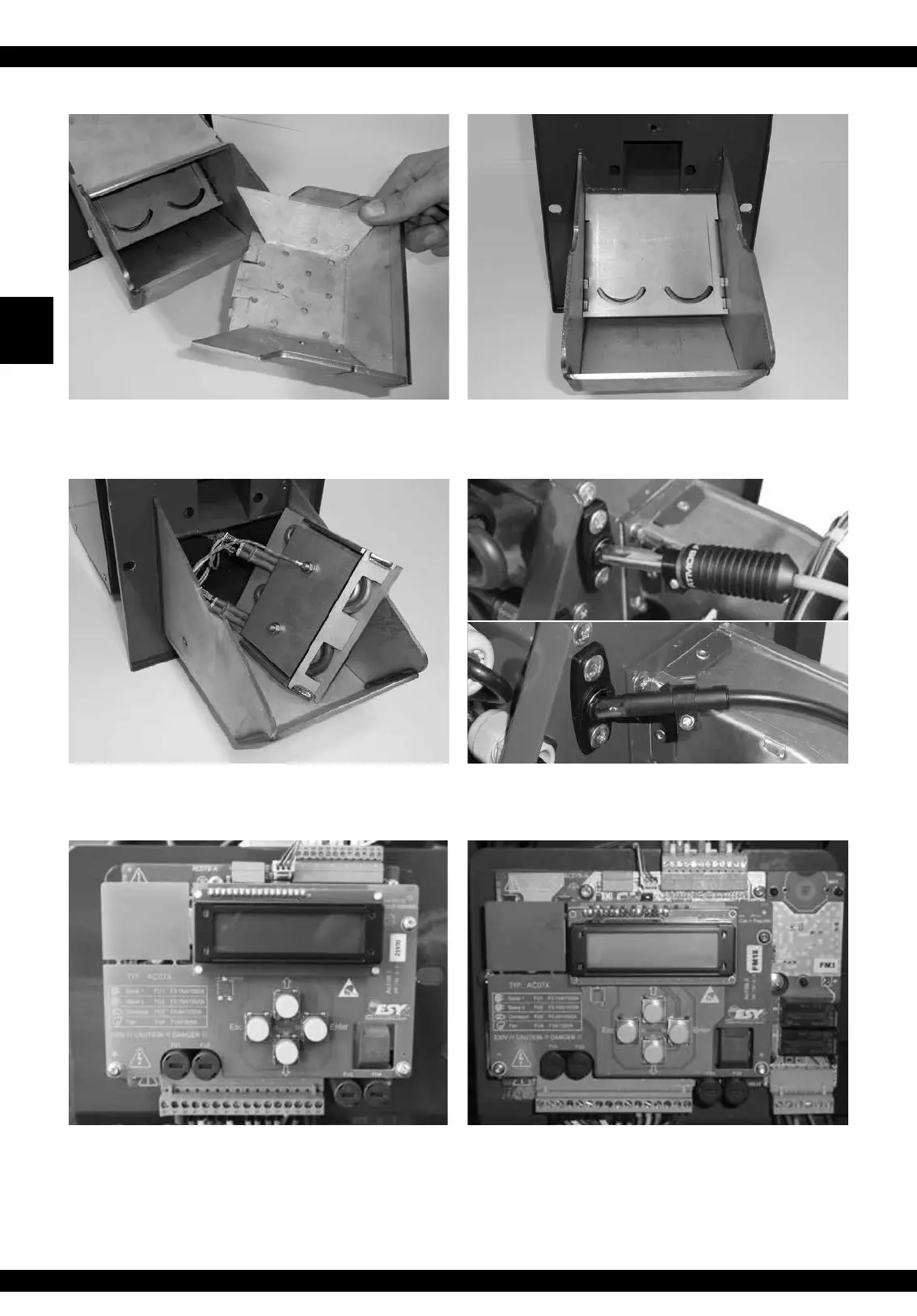
Fig. 3 - Disassembled plate with the ignition
spirals
Fig. 1 - Removable combustion chamber - must
be regularly cleaned
Fig. 2 - Uncovered combustion chamber with
openings behind which the ignition spirals are
installed
Fig. 4 - Photocell - be careful about its proper
orientation - we recommend you to clean it at
least once a year new fotocell/ old fotocell
Fig. 5 - Electronic control unit with keys, bottom
terminal board (1 - 18), upper distribution frame
for connection of TS, TV, TK, TSV sensors and
photocells
Fig. 6 - Electronic control unit with keys, in
version for DxxPX, PXxx, Pxx Compact boilers
with AC07X-C (R5, R6) additional module
 Loading...