⑦
W h e n w o r k i n g , f i r s t l o o s e n t h e l o c k n u t , t h e n m o v e t h e l a s e r u p a n d d o w n t o a n
a p p r o p r i a t e h e i g h t ( t h e d i s t a n c e f r o m t h e f i x e d f o c u s o f t h e o b j e c t t o b e e n g r a v e d ) , a n d
t h e n l o c k t h e l o c k n u t , a n d t h e l a s e r p r e p a r a t i o n i s c o m p l e t e .
①
②
③
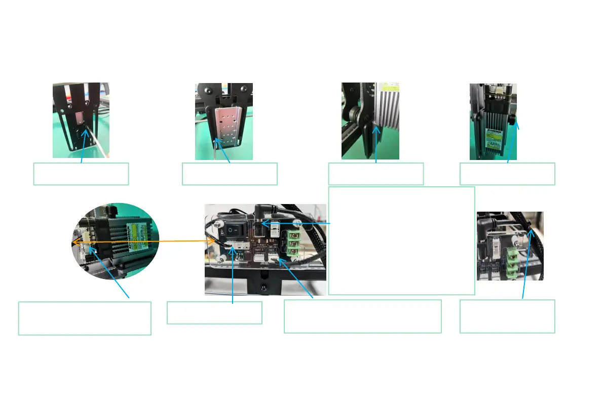
①.Install the slider
screw and tighten it
②.Tighten the slide rail
locking screws
③.Insert the laser into
the slider
④.Tighten the laser lock
nut
⑤. Connect the 3pin signal from
the switch board and insert the
3pin port of the laser
⑥.2 Auxiliary power supply: It is
recommended that the power adapter
below 12V3A should be plugged into the
auxiliary power supply, and the auxiliary
power supply is not required for 12V 3A
(inclusive) and above. Of course, this may
be different depending on the specific
model, as long as the laser power can
reach the maximum output power, there
is no need for an external auxiliary power
supply
⑥.1. Insert 3PIN signal
output terminal
⑥.3. According to the number of input
signals, insert the corresponding input
terminals (see Part 4 for details)
⑦.Fix the 3PIN signal
output line with a cable
tie
④
⑤
P a r t 5 : i n s t a l l a t i o n s t e p s
⑥
 Loading...