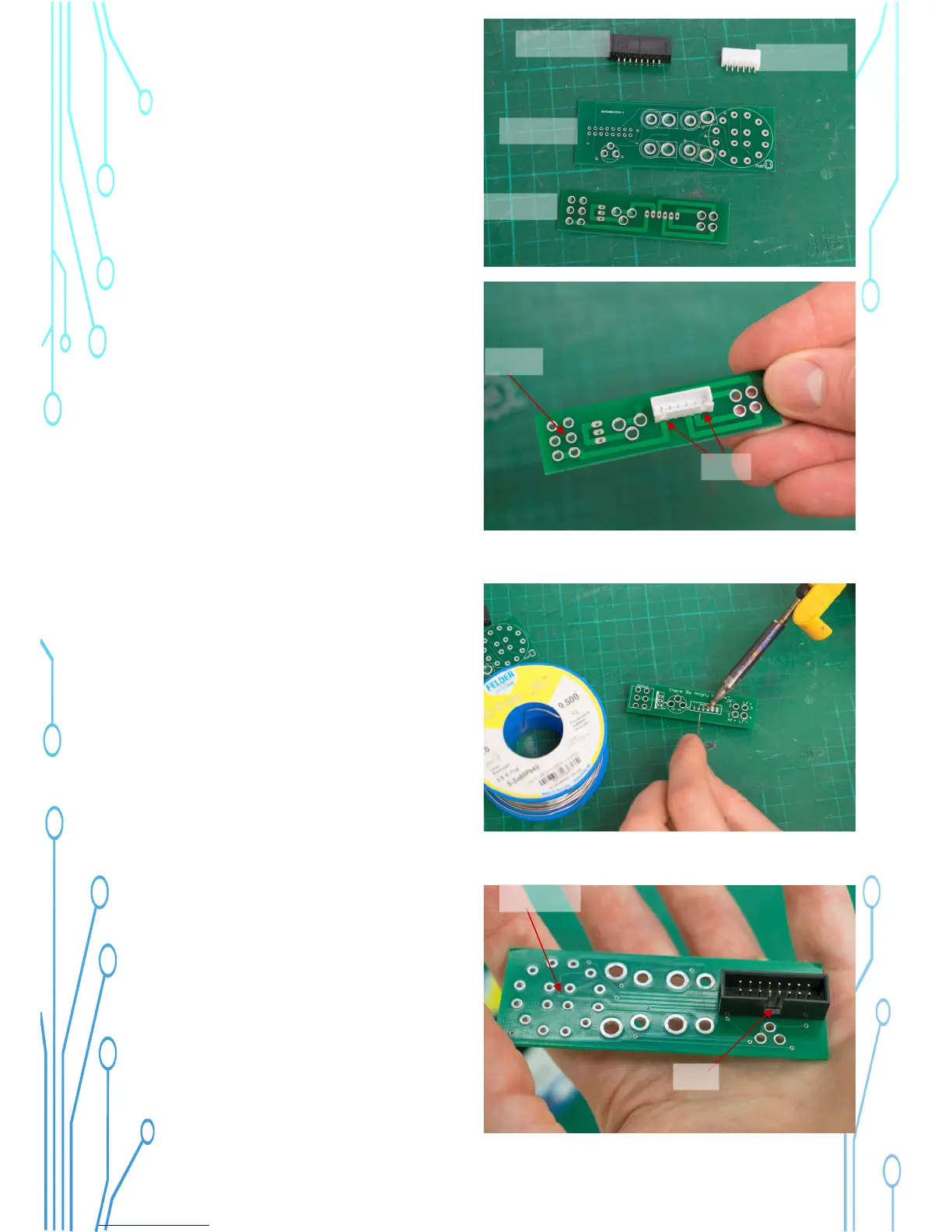
32) Now we install a connector socket on
each PCB.
Face the Power PCB with the printing
facing against the table and the 6 holes
on the left, as pictured.
Note: Print side down!
Insert the Power Connector as shown, the
gaps face towards you.
Ribbon Socket
Power Socket
Switch PCB
Power PCB
6 holes
Gaps
33) Turn the PCB over and solder the
pins.
34) Face the Source PCB with the
printing to the table. The large circle
should be on the left side.
Note: Print side down!
Install the ribbon socket as shown, please
see the gap in one side.
Gap
Large circle