4.2. Multi-turn actuator mounting to valve/gearbox
4.2.1 Output drive types B1, B2, B3, B4, B, and E
Application For rotating, non-rising valve stem.
Design Output drive type bore with keyway:
Type B1 – B4 with bore according to ISO 5210.
Type B and E with bore according to DIN 3210.
Later change from B1 to B3, B4, or E is possible.
Information Spigot at flanges should be loose fit.
Mounting the multi-turn actuator
1. Check if mounting flanges fit together.
2.
Check whether bore and keyway match the input shaft.
3. Thoroughly degrease mounting faces of the mounting flanges.
4. Apply a small quantity of grease to the input shaft.
5. Mount multi-turn actuator and ensure that the spigot mates uniformly in
the recess and that the mounting faces are in complete contact.
6. Fasten multi-turn actuator with screws according to table 1.
7. Fasten screws crosswise with a torque according to table 1.
12
Multi-turn actuator SAExC 07.1 – SAExC 16.1/SARExC 07.1 – SARExC 16.1 Non-Intrusive
with actuator controls AUMATIC ACExC 01.1 Profibus DP Operation instructions
2
13
4
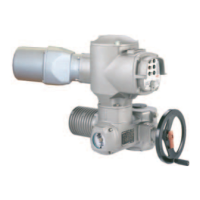
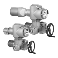
Figure 5
1 Output drive type B1/B2 and B 3 Output drive B3/B4 and E
2 Hollow shaft with keyway 4 Plug sleeve
with bore and keyway
Mounting flange Screws
Thread
Fastening torque T
A
[Nm]
Strength class 8.8
F07 M8 25
F10 M10 51
F14 M12 87
F16 M16 214
Table 1
Danger of corrosion due to damage to paint finish and condensation!
Ò
Touch up damage to paint finish after working on the device.
Ò
After mounting, connect the device immediately to electrical mains to
ensure that heater reduces condensation.
NOTICE
 Loading...