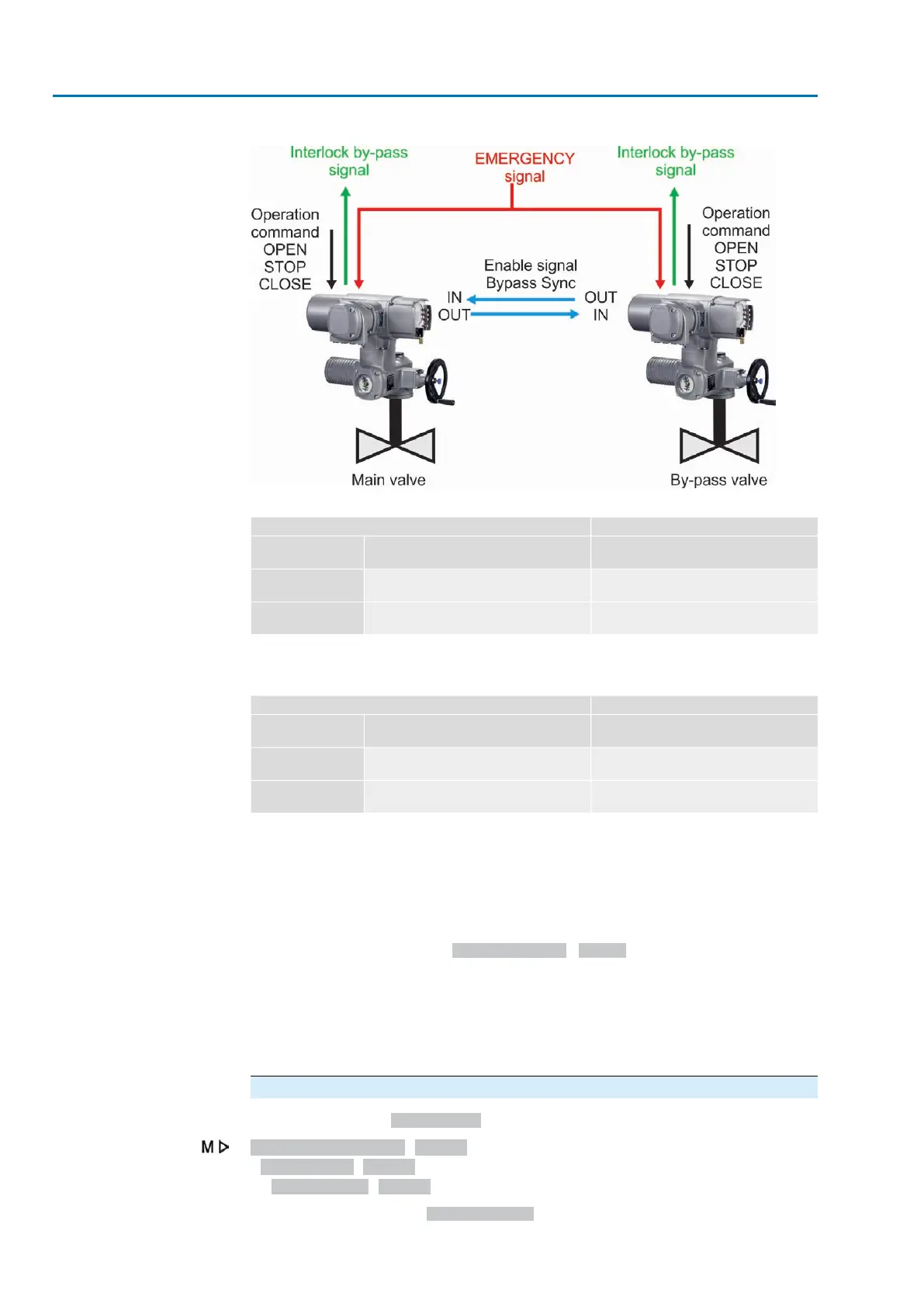
Figure 46: Function
Table 9: Main valve reaction to by-pass valve position.
Main valveBy-pass valve
Release
(available operation commands)
Enable signal
Bypass Sync OUT
Position
in directions OPEN and CLOSEHigh level (release)
(Default: +24 V DC
End position OPEN
No operation possible
1)
Low level (interlock)
(0 V DC or input open-circuit):
Other position
In case of an operation command, the "Interlock by-pass" signal is sent (no release).1)
Table 10: By-pass valve reactions to main valve position
By-pass valveMain valve
Release
(available operation commands)
Enable signal
Bypass Sync OUT
Position
in directions OPEN or CLOSEHigh level (release)
(Standard: +24 V DC)
End position
CLOSED
In direction OPEN or CLOSE
1)
Low level (interlock)
(0 V DC or input open-circuit):
Other position
In case of an operation command in direction CLOSE, the "Interlock by-pass" signal is sent (no re-
lease).
1)
EMERGENCY behaviour
The emergency behaviour of the by-pass function has the same characteristics as
the <EMERGENCY behaviour> function with the following differences:
In an EMERGENCY situation, both controls receive the EMERGENCY signal at the
same time.This signal starts the EMERGENCY operation specially defined for the
by-pass function. (Parameter EMCY operation M0204 is therefore not available in
the <EMERGENCY behaviour> function).
EMERGENCY operation procedure
1. By-pass valve is opened first.
2. Once the by-pass valve is fully opened, the main valve is closed.
3. Once the main valve is fully closed, the by-pass valve is fully opened.
Configuration of digital inputs
Required user level: Specialist (4) or higher.
Device configuration M0053
I/O interface M0139
Digital inputs M0116
Example
Use input DIN4 for signal Bypass Sync In:
66
Actuator controls
Application functions ACV 01.2/ACVExC 01.2

 Loading...