Ⅲ.FEATURES
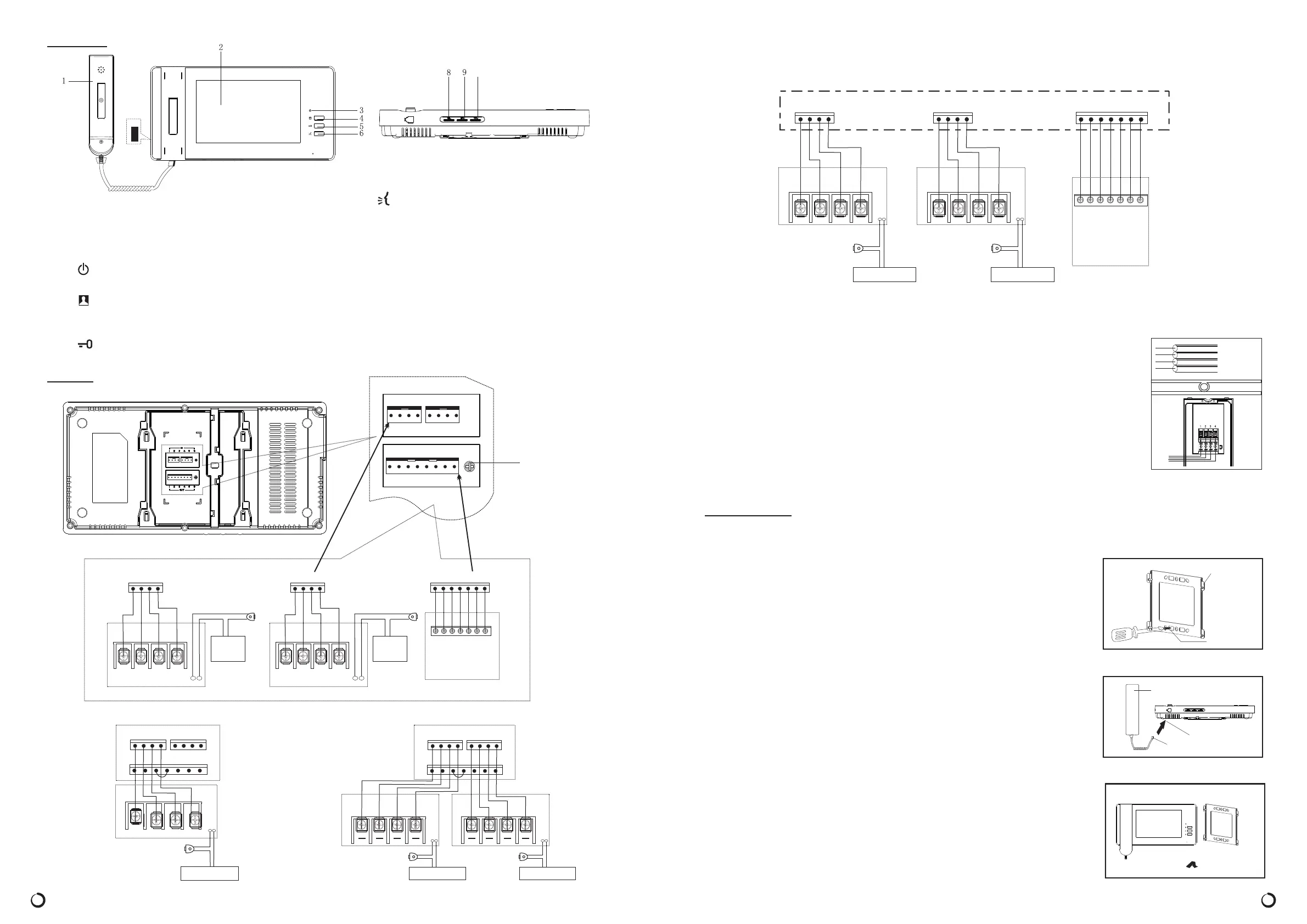
Ⅳ.WIRING
2
O U T D O O R 1
O U T D O O R 2
I M A G E
1 2
5
#3 6#4 7
ImageMemory
(
)
Optional
Accessories
1
2
5
3 6
4
7
Release
Camera1
4
1 2 3 4
32
1
Door
A - 1 2 1 /
A - 1 2 2
Power
(
)
Optional
Accessories
1 2 3 4
Release
Camera2
432
1
Door
A - 1 2 1 /
A - 1 2 2
Power
(
)
Optional
Accessories
6. Talk Button
7. Power “O/I” S/W
Used to turn AC power“O” and“I”
8. COL Contrast ControL
To control contrast of screen, to control chroma
of LCD
9. BRI Brightness Control S/W
Used to adjust brightness level of the Screen.
10. VOL Volume Control
11. Ringtone Volume Control
1. Handset
Used for two-way communication with the v isitor.
2. Screen
Displays image of a visitor o r the camera viewing
area.
3. Power LED
Illuminates when power S/W is in “ON” position.
4. Monitor Button
Press to activate the outside camera and screen to
see c amera viewing area.
5. Door Release Button
Used to unlock an electronic door locking system.
1 0
Camera2
Camera1
44
33 22 11
Door
Release
Door
Release
Power ( ) Optional AccessoriesPower ( ) Optional Accessories
A- 121 / A - 1 2 2A- 121 / A - 1 2 2
INDOOR PHONE
11
22 33
44
O U T D O O R 1 O U T D O O R 2
7
6#3
5
2
#4
1
I M A G E
Door
Release
4
321
INDOOR PHONE
Camera2
A-1 21 / A- 1 22
Power ( ) Optional Accessories
11
22 33
44
O U T D O O R 1 O U T D O O R 2
7
6#3
5
2
#4
1
I M A G E
OU T DO OR 1 OU T DO OR 2
I M A G E
11
1
1 2 3 4 5 6 7 8
2 3 4 1 2 3 4
VOL
Mounting
Bracket
Mounting
Screw
3
Handset
Indoor Phone
Plug
AC SWITCH
Note: Using the component “2# Line” to connect #3,#4 shut pin when you are not using image
memory
Wiring is not supplied with your Video Doorphone system.Use only AWG #22 wire (0.65mm,
4-wire) and follow the appropriate wiring diagrams exactly for optimum system performance
and safety.
When planning to install the initial system , consider future system extension. The total wire
length for a single camera and monitor system(or any combination of additional camera or
monitors) must not exceed 50m for optimum performance.
* OPTION 2 (TWO CAMERAS/ INDOOR PHONE/IMAGE MEMORIER)SINGLE
Ⅴ.INSTALLATION
Important Mounting Notes:
Do not install the monitor and camera units where they will be exposed to dirt,
direct sunlight (or other strong light) , moisture ,high temperature 40℃ )
or high humidity conditions.
Do not select an installation location subjected to vibration or pounding.
Select a mounting location
close to an
AC outlet where it is easy to view the
screen and operate the monitor.
( over
1. Determine the mounting locations for the outside camera
inside monitor.
2. At the selected monitor mounting location , attached the mounting bracket
securely to t h e wall, drill a h ole in the center area of the bra cket just large
enough for the electrical wirin g to pull through the hole. Connect the electrical
w ires from the camera unit to the monitor..
3. Connect the handset cord to the monitor unit.
4. Attach the wired monitor unit to the wall mounting bracket by setting the
monitor over the four bracket hooks and sliding it down , Insert the tiny
machi ne s crew into the hole in the tab at the top of the bracket to hold the
monitor in place.
5. Plug the AC power cord into a standard household outlet.
6. Place the power“ON/OFF”switch on the “On” position.
both and
AWG 22
Wrie
(0. 65mm)
7
o
I
INDOOR PHONE
Power ( ) Optional AccessoriesPower ( ) Optional Accessories
I M A G E
1 2 5#3 6#4 7
Image Memory
(
)
Optional
Accessories
1
2
5
3 6
4
7
O U T D O O R 2
1
2 3
4
Door
Release
Camera2
A-1 2 1 / A-1 2 2
4
321
O U T D O O R 1
1
2 3
4
Door
Release
Camera1
A-1 2 1 / A-1 2 2
4
321
 Loading...