Table of Contents
Introduction . . . . . . . . . . . . . . . . . . . . . . . . . . . . . . . 2
Series 255/460i Demand Control System
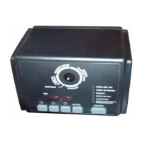
460i Electronic Demand System
Installation . . . . . . . . . . . . . . . . . . . . . . . . . . . . . . . . 5
Location Selection
Water Line Connection
Drain Line Connection
Brine Line Connection
Overflow Line Connection
Splicing Low Voltage Transfer Cord. . . . . . . . . . . . 6
Placing Conditioner Into Operation . . . . . . . . . . . . 6
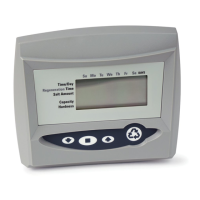
Programming the 460i . . . . . . . . . . . . . . . . . . . . . . . 7
Manual Regeneration . . . . . . . . . . . . . . . . . . . . . . . 8
Adjustment of Brine Control . . . . . . . . . . . . . . . . . . 9
Removing the 255 Control Module for Servicing 10
Specification. . . . . . . . . . . . . . . . . . . . . . . . . . . . . . 11
Pressure Graphs . . . . . . . . . . . . . . . . . . . . . . . . . . 12
Control Valving Identification . . . . . . . . . . . . . . . . 12
Valve Disc Operation . . . . . . . . . . . . . . . . . . . . . . . 12
Flow Diagrams . . . . . . . . . . . . . . . . . . . . . . . . . . . . 12
Replacement Parts . . . . . . . . . . . . . . . . . . . . . . . . 14
Preventive Maintenance . . . . . . . . . . . . . . . . . . . . 18
Injector Screen and Injector
Water Meter
Troubleshooting . . . . . . . . . . . . . . . . . . . . . . . . . . . 19
Introduction
Series 255/460i Demand Control System
The Series 255/460i demand control system combines
design simplicity with reinforced Noryl* construction to
provide the user with an uncommonly reliable
appliance. The inherent reliability of the system means
a long life of efficient, trouble-free, uninterrupted soft
water luxury.
Should maintenance become necessary, the
Series 255 offers a unique “separation” capability
illustrated in this manual.
Of interest to both the owner and the water
conditioning dealer are the design and operation
benefits detailed below.
Superior Design
• Fewer parts than any control system of
comparable function and most controls of lesser
function.
• Single synchronous electric motor provides all
the power needed to turn the camshaft.
• 460i timer utilizes a microprocessor to provide a
time-proven logic analysis to initiate regeneration.
• Electrical wiring is factory assembled. System
cannot be connected incorrectly.
• System indexes manually with or without power
to any one of its service or regeneration positions.
Readout on timer face plate indicates control valve
position.
• No dynamic seals that could cause leakage
through wear or fatigue.
• Control accepts Noryl or brass manifold or
modular bypass valve without modification,
offering complete versatility and easy plumbing for
any installation.
• Brining control valve built into system eliminates
need for an external brine valve.
• Automatic drain flow controller is incorporated
into the system.
Superior Operation
• Direct acting system functions independently of
water pressure. No pistons or diaphragms that
require a minimum water pressure to operate.
• Five-cycle operation provides for downflow
service, upflow backwash, downflow brining,
downflow rinse, downflow purge, or fast rinse. A
sixth position is included for timed refill of the brine
tank.
• Valve discs are held closed by water pressure
and therefore are leak tight. The sealing forces are
increased as the water pressure is increased. Valve
seats are in a vertical position, which is the design
position least vulnerable to plugging.
• System operation cannot get out of phase or
sequence. Control always returns to a fixed service
position after regeneration regardless of where in
the regeneration cycle it was started.
• Bypass water is automatically available during
regeneration.
*Noryl is a trademark of General Electric Company
 Loading...