Important: Never connect drain line into a drain, sewer
line or trap. Always allow an air gap between the drain
line and the wastewater to prevent the possibility of
sewage being back-siphoned into conditioner.
Figure 5
Note: Standard commercial practices have been
expressed here. Local codes may require changes to
these suggestions.
Brine Line Connection
It will be necessary to install the brine tube and connect
the line to a fitting installed on the air check.
Be sure all fittings and connections are tight so that
premature checking does not take place. Premature
checking is when the ball in the air check falls to the
bottom before all brine is drawn out of the brine tank.
See Placing Conditioner into Service section.
Overflow Line Connection
To connect overflow, locate the hole on the side of the
brine tank. Insert overflow fitting (not supplied) into tank
and tighten with plastic thumb nut and gasket as
shown (Figure6). Attach length of 1/2-inch (1.3-cm) I.D.
tubing (not supplied) to fitting and run to drain. Do not
elevate overflow line higher than 3 inches (7.6 cm)
below bottom of overflow fitting.
Figure 6
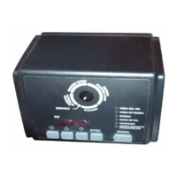
Electrical Connection
12VAC:
The power supply transformer should have a minimum
rating of 3 volt-amps. Connect the plug of the
transformer secondary cable to the mating socket on
the bottom of the controller.
Be certain the transformer is plugged into a
source that is not controlled by a wall switch and
cannot be accidentally turned off.
Splicing the Low Voltage
Transformer Cord
If it is necessary to extend the length of the transformer
cord, an optional 15-foot (4.6-m) extension cord is
available (P/N 1000907), or the cord may be spliced as
follows:
1. Strip insulation from wire 5/16 inch (.8 cm) from wire
end.
2. Insert stripped wire into barrel of connector and
crimp. For best results, crimp twice per wire as
shown in Figure7.
Splice connectors or extension wire is not supplied.
They are available at hardware or electrical stores.
Figure 7
Placing Conditioner into
Operation
After all previous steps have been completed, the unit
is ready to be placed into operation. Follow these steps
carefully:
1. Remove control valve cover (Figure 14).
Note: The following steps will require turning the
pointer knob (Figure9) to various positions. Insert a
wide-blade screwdriver into arrow slot in pointer
knob and press in firmly. With knob held in, rotate
COUNTERCLOCKWISE only until arrow or knob
points to desired position. (Rotation is made much
easier if you grasp the camshaft with your free hand
and turn it at the same time.) Then permit knob to
spring back out.
2. Insert screwdriver into slot in pointer knob
(Figure9). Press in and rotate knob
 Loading...