COUNTERCLOCKWISE until arrow points directly
to the word BACKWASH.
3. Fill resin tank with water.
A. With water supply off, place the bypass valve(s)
into the “not in bypass” position.
B. Open water supply valve very slowly to
approximately the 1/4 open position.
Important: If opened too rapidly or too far, resin may
be lost. In this position, you should hear air escaping
slowly from the drain line.
C. When all of the air has been purged from the
tank and clear water begins to flow steadily
from the drain, close main supply valve.
D. With the water supply off, let the unit stand for
about five minutes. This will allow all trapped air
to escape from the tank.
E. Proceed to step 4.
4. Add water to brine tank (initial fill). With a bucket or
hose, add approximately four gallons (15 liters) of
water to brine tank. If the tank has a salt platform
above the bottom of the tank, add water until the
level is approximately 1 inch (25 mm) above the
platform.
Figure 8
5. Put into operation.
A. Open water supply valve slowly to full open
position.
B. Carefully advance pointer knob
COUNTERCLOCKWISE to center of FAST
RINSE/REFILL position and hold there until air
check (Figure1) fills with water and water starts
to flow through brine line into brine tank. Do not
run for more than two minutes.
C. Advance pointer knob COUNTERCLOCKWISE
until arrow points to the center of the BRINE/
SLOW RINSE position.
D. With the conditioner in this position, check to
see if water is being drawn from the brine tank.
The water level in the brine tank will recede very
slowly. Observe for at least three minutes. If the
water level does not recede or goes up, or if air
enters the transparent air check chamber and
the ball falls and seats, reference
Troubleshooting section.
E. Advance pointer knob COUNTERCLOCKWISE
to CONDITIONED WATER.
F. Run water from a nearby faucet until the water
is clear and soft.
Programming the 460i
Plug the wall mount transformer into a functioning
electrical outlet that is not controlled by a switch. Plug
the transformer plug into the transformer plug
receptacle on the timer.
Note: If the included transformer cord is not long
enough, a 15-foot (4.6-m) extension is available. See
Splicing the Low Voltage Transformer Cord section
of this manual.
Open the access door by pushing the raised tab on the
door toward the left while pulling the tab out (Figure9).
Figure 9
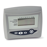
Time of Day Setting
With the jumper on the set of pins next to the word
TIME (Figure 10), set the time of day to the closest hour
by pressing the black TIME SET button. PM hours are
indicated by a light next to the letters PM on the display
window.
255/460i shown with optional i-lid cover (PN 1000062)
PM Indicator
Water Flow Indicator
Hour Time Display
Access Door
Pointer Knob
Time Set Button
Transformer Plug
Receptacle
Jumper
Spare
Raised
Tab
Jumper
 Loading...