Do you have a question about the AVALITES Sunny 512 and is the answer not in the manual?
Details DMX512/1990 standard, 512 channels, 2 optical isolated outputs, and wide voltage range.
Specifies maximum 32 scanners, 16 channels per scanner, and 16-bit X/Y movement.
Highlights the backlight LCD, 16 channel sliders, and 1 speed control slider.
Covers 1600 chase steps, 48 chases, 48 scenes, and simultaneous operation.
Includes 16-bit control, modulation wheel for X/Y, 15 environment programs, and music trigger.
Mentions data auto-saves and high-performance switching power supply.
Warns about high voltage inside the equipment and the need for earth line connection.
Advises against opening the equipment and splashing liquids to prevent damage.
Prohibits plugging/unplugging DMX cables while the power is on to protect components.
Details the console's two optical isolated DMX512 signal independent drive devices.
Provides the pinout (1-Screen net, 2-Signal-, 3-Signal+) for the DMX data cable.
Recommends a 120Ω matching resistor at the end of the DMX cable for signal quality.
Explains the console distributes addresses with a fixed space of 16 channels.
Illustrates binary switch settings for scanner addressing.
Notes address set differences and how to adjust for 000-511 vs 001-512 ranges.
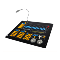
Presents the overall layout of the Sunny 512 controller's front panel.
Describes the function of CLEAR, 1-16 Section, 17-32 Section, and HOLD keys.
Explains the use of 1-16 scanner number keys for selecting scanners.
Details how 16 channel sliders set values for the chosen scanner in manual state.
Covers saving 48 scenes across 3 sections, with 16 scenes per section.
Explains A/B/C section keys and 1-16 scene number keys for operation.
Describes the SINGLE scene key for running one scene at a time per section.
Details saving 48 chases across 3 sections, with 16 chases per section.
Explains A/B section keys for accessing chases within different sections.
How to select and run environments using SELECT and number keys.
Covers SAVE TO SCENE and SAVE TO ENV keys for storing scene and environment data.
Details the EDIT CHASE key for entering chase editing mode.
Explains the SET X/Y key for configuring scanner X/Y channel assignments.
Describes the ADD and DELETE keys for managing chase steps during editing.
Explains the ENTER/SWITCH key for scene, environment, and chase editing.
Details the modulation wheel for X/Y and the SPEED slider for chase speed.
Describes the MUSIC trigger and BLACKOUT keys for special operations.
Identifies the main POWER switch for the equipment.
Details the two DMX512 output sockets with identical signals.
Describes the 1/4" mono socket for audio input or internal microphone trigger.
Covers the power input socket and the location of power fuses.
Explains 8-bit (2 channels) and 16-bit (4 channels) X/Y control for scanners.
Provides a step-by-step guide on how to set scanner X/Y channel parameters.
Illustrates X/Y channel setting examples for both 8-bit and 16-bit scanners.
Discusses how setting X-L/Y-L to 'no' results in 8-bit X/Y resolution for 16-bit scanners.
Explains the console automatically corrects X-L and Y-L settings to 'no' simultaneously.
Outlines steps to check the X/Y settings of scanners using the SET X/Y key.
Details manual control of channel values and X/Y positions using sliders and modulation wheel.
Step-by-step guide for manually operating a single scanner.
Procedure for manually operating multiple scanners of the same X/Y channel type.
Method for manually operating different types of scanners sequentially.
Explains how to cancel manual operation and that settings are not saved.
Describes scenes as aggregates of scanner channel values for light art patterns.
Provides advice on channel values for simultaneous scene/chase running (HTP Technique).
Outlines the steps for saving current scanner states as a scene.
Notes that scene editing can be performed at any time, saving current states.
Demonstrates how to copy one scene to another.
States the console can save 48 chases, each up to 100 steps.
Explains a chase step includes channel values, step time, and cross parameter.
Defines Step Time (0.1s-60s) and Cross Value (0-100%) for chase steps.
Describes pressing the EDIT CHASE key to enter chase editing mode.
Guides on choosing a chase number and using ADD key to insert steps.
Explains using the modulation wheel to adjust STEP, TIME, and CROSS values.
Details setting scanner channel values manually within a chase step.
Provides advice on copying steps and managing empty chases.
Explains environments save current states (manual, scene, chase) for easy reuse.
Covers saving complex combinations of operations as a single environment.
Outlines the steps to save the current environment to a specific number.
Notes that SELECT key is not needed to save an environment.
Details the procedure for running a single scene, like A01.
Explains how to run multiple scenes concurrently, e.g., A02, A10, B5, C07.
Provides instructions for running a single chase, such as A08.
Guides on running multiple chases concurrently, e.g., A04, A13, B07, C10.
Describes how to view parameters of multiple running chases.
Explains using the SPEED slider to adjust the operating speed of a chase.
Details activating the MUSIC key for music in-phase chase triggering.
Guides on running environments by pressing SELECT and a number key.
Covers DMX512/1990 mode, channel amount, scanner control, and distribution.
Details scanner amount, channel distribution per scanner, and resolution (16bit).
Specifies manual operation ability, scanner scenes, and simultaneous scene/chase amounts.
Lists max chase steps, step time, cross ratio, total chase steps, and simultaneous chases.
Covers music in-phase chase, channel sliders, speed slider, and modulation wheel specs.
Details chase speed ratio range, environment count, and scene copying capability.
Specifies DMX connectors (XLR-D3F x 2), audio input (1/4"), and AC power range.
Lists power consumption (15W), operating temperature (0-40°C), IP rating, and dimensions.
| Brand | AVALITES |
|---|---|
| Model | Sunny 512 |
| Category | Music Mixer |
| Language | English |