Do you have a question about the Avermedia D315 Series and is the answer not in the manual?
Visual representation of system components and their connections.
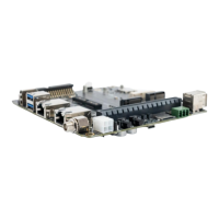
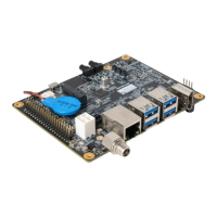
Images showing the front and back of the carrier board.
Identifies connectors visible from the top of the carrier board.
Identifies connectors visible from the bottom of the carrier board.
Details the connector for the NVIDIA Jetson module.
Describes the connector for the fan power supply.
Details the connector for the Real-Time Clock battery.
Information about the HDMI output connector.
Details the dual USB 3.2 Gen 2 Type-A connectors.
Information about the M.2 E key slot for 2230 form factor.
Information about the M.2 M key slot for 2280 form factor.
Details the USB 2.0 Micro B connector for recovery.
Information about the Micro SD card slot.
Details the 10 Gigabit Ethernet connector.
Description of the 40-pin expansion header and its pinout.
Details the audio pin header and its pinout.
Information about the Gigabit Ethernet connector.
Details the Micro SIM card socket.
Information about the Mini card socket.
Details the OOB (Out-of-Band) board connector.
Information about the 54V DC power input jack.
Details the ATX 4-pin power connector.
Details the dual USB 2.0 Gen 1 Type-A connectors.
Information about the 12V power input for daughter boards.
Details the PCIe x16 socket.
Describes the connector for connecting to a camera board.
Details the CAN Bus 3-pin terminal block.
Information about the debug port.
Details the switch button functionality.
Details the power and recovery control buttons.
Instructions for setting up the Board Support Package (BSP).
Details support for M.2 Wi-Fi/Bluetooth modules.
Information on how to manage power modes.
Command to get RTC battery voltage.
Commands to get and set PWM fan speed.
Instructions for enabling, setting up, and using the CAN Bus.
Lists supported cameras and test commands for them.
Details how to use GPIO pins for input and output.
Drawings and specifications for the fan module.
| Video Format | MPEG 4 |
|---|---|
| Operating System | Windows |
| Model | D315 |
| Software Included | AverMedia |
| Supported Resolutions | 720x576 (PAL), 720x480 (NTSC) |