03/10 Rev. 5.04-04 SERVICE MANUAL Service Mechanics
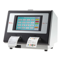
64-xx – 64-xx Dispenser
35
Feed unit
Construction of the feed unit
The complete feed unit (1) consists of the
following components:
– Feed rollers (x2)
– Contact roller unit
– Print head mounting
– Material guide
– Gap photoelectric switch
Feed rollers
Disassembling
1. Loosen and remove the stepper motor
feed (3 self-securing hexagonal nuts).
2. Remove the toothed belt feed.
3. Unscrew the thermal bar (thumb screw)
and lay it free.
4. Remove the retaining ring (2) on the
ratchet wheel and pull the ratchet wheel
(3) off the axle.
To pull off the ratchet wheel using a
strong screwdriver as a lever between
the ratchet wheel and the cast plate.
5. Loosen and remove the outer seating
collar (4) (2 Allan key screws).
Continued on the next page.
1
2
4
3

 Loading...