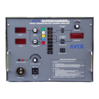
Operator Manual, Supercharger 60 R3.0
Page 1 of 62
TABLE OF CONTENTS
1. INTRODUCTION AND SYSTEM DESCRIPTION .................................................................. 5
2. CONDENSED OPERATING INSTRUCTIONS ....................................................................... 8
2.1 Constant Current Charge (normal mode) ............................................................................................... 8
2.2 Constant Voltage ........................................................................................................................................ 9
2.3 Peak Voltage Charge ............................................................................................................................... 10
2.4 Discharge .................................................................................................................................................. 11
3. SPECIFICATIONS ................................................................................................................ 12
3.1 CHARGE .................................................................................................................................................. 12
3.2 DISCHARGE ........................................................................................................................................... 14
3.3 TIMER ...................................................................................................................................................... 15
3.4 LINE INPUT VOLTAGE: ...................................................................................................................... 16
3.5 DIGITAL PANEL METERS .................................................................................................................. 17
3.6 FUSES and BREAKERS (Other than charge and discharge current limiters) ................................. 17
4. CONTROLS AND DISPLAYS .............................................................................................. 18
4.1 M1 - Ammeter .......................................................................................................................................... 18
4.2 M1 - Voltmeter ......................................................................................................................................... 18
4.3 R1 - Main Charge Current Selector ....................................................................................................... 18
4.4 R2 - Topping/Discharge Current Selector ............................................................................................. 18
4.5 SW1 - Main Time selector switch ........................................................................................................... 18
4.6 SW2 - Total Time selector switch ........................................................................................................... 18
4.7 SW3 – Keypad .......................................................................................................................................... 18
4.8 SW4 - CELL SELECTOR: ..................................................................................................................... 19
4.9 SW5 - DIGITAL VOLTMETER INPUT SELECTOR: ...................................................................... 19
4.10 SW6 - VOLTAGE MODE SELECTOR:............................................................................................... 19
4.11 SW7 - TIMER SPEED SELECTOR: .................................................................................................... 19
4.12 DS1A - RESET:........................................................................................................................................ 21
4.13 DS1B - CYC END: ................................................................................................................................... 21
4.14 DS2A - DUAL: ......................................................................................................................................... 21
4.15 DS2B - MAIN: .......................................................................................................................................... 21
4.16 DS3A - SINGLE: ...................................................................................................................................... 21
4.17 DS3B - TOP: ............................................................................................................................................. 21
4.18 DS4A - AUTO: ......................................................................................................................................... 21
4.19 DS4B - DISCH: ........................................................................................................................................ 21

 Loading...