Chapter 1: Introduction 3
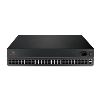
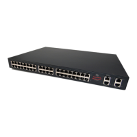
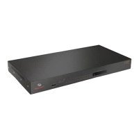
The following figure shows the rear connectors on the console server.
Figure 1.2: Rear of the Console Server (ACS6032 Console Server Shown)
AUX/MODEM Dual LED: Yellow on top, Green on bottom
• Yellow - DTR/DCD activity
• Green - TXD and RXD activity
• Off - No activity
[One LED for each serial port] Green
• Blinks - Ready, with activity
• Solid - Ready
• Off - Not ready
Table 1.3: Connectors on the Console Server Rear
Number Description
1 Power supplies (dual AC shown). Models come with either single or dual AC or DC power.
2 Serial ports (32 ports shown). Models come with 16, 32 or 48 serial ports to connect to device
consoles, power devices, or external modems.
3 ETH 1 10/100M/1G Ethernet port. Can be connected to a second network or used for failover.
4 AUX/Modem port - if an optional internal modem is ordered, this port is defined as a V.92
modem at the factory and can be used to connect the console server to a dedicated phone
line; otherwise, the port is factory-defined as RS-232 with an RJ-45 Cyclades pin-out and can
be used to connect either an external modem or a power device.
5 ETH0 10/100M/1G Ethernet port for remote IP access.
6 Console port allows for local administration and access to connected devices through a
terminal or a computer with a terminal emulator.
Table 1.2: LEDs on the Console Server Front (Continued)
Label Description
 Loading...