vii
List of Figures
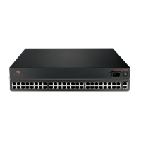
Figure 1.1: Front of the Console Server with PC Card Slots and LEDs (ACS6032 Console Server
Shown) ............................................................................................................................................2
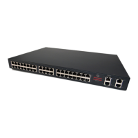
Figure 1.2: Rear of the Console Server (ACS6032 Console Server Shown).................................. 3
Figure 1.3: Typical ACS 6000 Advanced Console Server Configuration ......................................4
Figure 2.1: Bracket Connections for Front Mount Configuration...............................................13
Figure 2.2: Example: Daisy-chained Cyclades PDUs ................................................................. 16
Figure 2.3: DC Power Connection Terminal Block.....................................................................17
Figure 3.1: Administrator Web Manager Screen ......................................................................... 26
Figure 3.2: Web Manager Regular User Screen..........................................................................29
Figure 8.1: Power Configuration of AUX/Modem or Serial Port................................................61
LIST OF FIGURES
 Loading...