Do you have a question about the AVR SX440 and is the answer not in the manual?
Defines voltage and frequency range for sensing input.
Details voltage, current, and resistance limits for the output.
Specifies the voltage regulation accuracy.
Steps to adjust output voltage using VR or external trimmer.
Procedure to adjust stability control for steady output.
How to adjust droop using quadrature droop CT signal.
Process to ensure residual magnetism for voltage build-up.
Caution against damage from incorrect field flashing.
Identifies common symptoms, causes, and corrections.
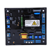
The SX440 is a Generator Automatic Voltage Regulator (AVR) designed for self-excited generators, providing stable voltage output and various control features. Its primary function is to maintain the generator's output voltage within specified limits, ensuring reliable power delivery.
The SX440 operates by sensing the generator's output voltage and adjusting the excitation current to the generator's field winding. This closed-loop control system ensures that the voltage remains constant even under varying load conditions. It incorporates several protective features, including under-frequency protection, which safeguards the generator from damage when operating below its nominal frequency. The AVR also includes a soft start ramp time, allowing for a gradual voltage build-up during startup, which helps to prevent sudden electrical surges and stress on the generator and connected equipment.
For applications requiring parallel operation with other generators or a utility bus, the SX440 offers parallel compensation capabilities. This involves integrating a current transformer (CT) to provide a droop signal, ensuring proper load sharing and reactive power distribution among parallel sources. The reactive droop compensation feature allows for precise control of reactive power, which is crucial for stable parallel operation.
The AVR's design allows for both internal and external voltage adjustment. Users can fine-tune the output voltage using a trimmer on the AVR board or through an optional external trimmer, offering flexibility in system configuration and operation. Stability adjustment is also provided, enabling users to optimize the AVR's response to load changes and prevent voltage oscillations.
The SX440 is designed for straightforward installation and operation. Its compact dimensions make it suitable for mounting in various locations, including directly on the engine, genset, switchgear, or control panel, provided the chosen position does not affect its operation. Clear wiring diagrams are provided to guide users through the connection process, ensuring correct installation.
Before starting the generator, users are instructed to set the internal voltage trimmer to its minimum position and the external trimmer (if fitted) to its midway point. The stability trimmer should also be set to midway. Once the generator is running at its nominal frequency, the voltage trimmer can be carefully adjusted clockwise until the desired rated voltage is achieved. If an under-frequency condition is detected, indicated by a red LED, users are directed to refer to the under-frequency roll-off adjustment procedure.
The AVR supports different power output ranges, with specific link configurations (A, B, C) for generators under 90KW, between 90-550KW, and over 550KW. This adaptability ensures compatibility with a wide range of generator sizes. Jump select terminals (J1-J8) offer further configuration options, allowing users to customize the AVR's behavior according to specific application requirements.
For parallel operation, the SX440 requires a 10VA current transformer (CT) connected in a generator line. The CT's phase relationship to the regulator sensing voltage is critical for proper parallel functionality. A unit-parallel switch can be used to short the parallel CT secondary during single-unit operation, preventing droop signals from affecting the regulating system.
The SX440 incorporates features that facilitate troubleshooting and maintenance. A dedicated section in the manual outlines common symptoms, their probable causes, and corresponding corrective actions. For instance, if the generator voltage does not build up, potential causes include low engine speed, incorrect wiring, a defective generator, or a broken external VR. The manual directs users to check wiring, refer to diagrams, or consult the generator manual for solutions.
In cases where residual magnetism is insufficient for voltage build-up, the manual provides a detailed field flashing procedure. This involves applying a low-voltage DC source to the generator's field winding to re-establish the necessary residual voltage. Users are cautioned against excessive field flashing, as it can damage the AVR or the generator's excitation winding. The importance of understanding the instruction manual before installation is emphasized to prevent irreversible damage due to incorrect wiring.
The AVR is designed with live terminals and a heatsink, posing an electric shock risk, which is clearly indicated by a warning label. This highlights the need for caution during installation and maintenance. For fuse replacement, users are advised to use only original supplied spare protection fuses. The manufacturer also notes that modifications in performance, specification, or appearance may occur without prior notice, indicating a commitment to continuous improvement.
| Power Input Frequency | 50/60Hz |
|---|---|
| Current Rating Continuous | 4 A dc |
| Under Frequency Protection 50Hz | 47Hz |
| External Volts Adjustment | +/-10% |
| Operating Temperature | -40 to +70°C |
| Storage Temperature | -55 to +80°C |