- 36 -
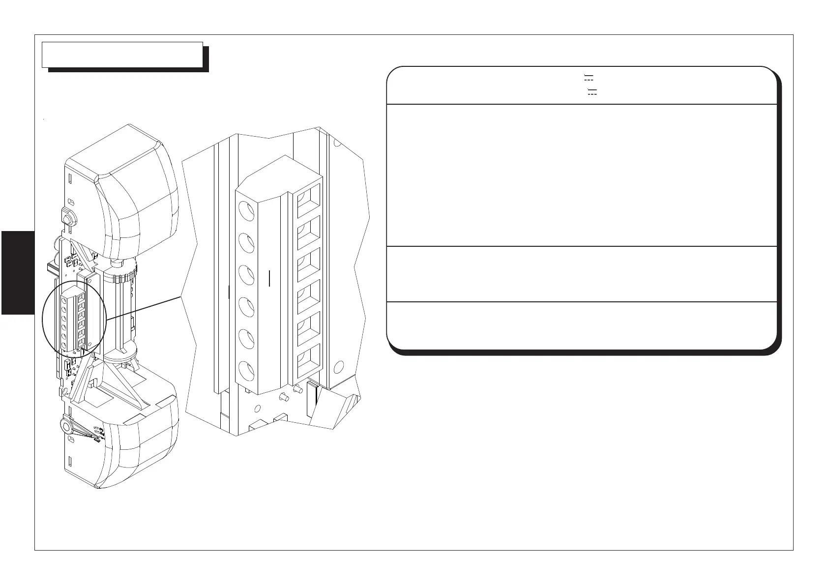
The terminal board is placed on the
bottom side of the circuit as shown
in the picture.
+
-
AM
B C
NC
NO
Anti - Masking
The Anti-Masking feature provides a supervision trouble signal if microwave
reflective material (i.e. metal, wood, some plastics, etc.) is placed within 50 cm of
the detector.
NOTE: This function DO NOT warrants against sensor masking attempts
A possible alarm, caused by masking attempt, is kept in memory by yellow led and an AM output is
activated.
AM terminal gives a transistorized negative when anti-masking circuit is active.
Both led and output negative are reset at first alarm triggered off by the detector.
Open the jumper S5 to exclude the Anti - Masking function (output and yellow led ).
+
-
B
AM
C
NC/NO
Supplying positive 12 V
Supplying negative 12 V
Input which allows the detector to know the control unit
condition. At disarmed system this input must be closed to
positive, in this condition the detector behaves as follows:
• alarm relay remains closed (activation after 5 sec. from
absence of positive on terminal B)
• if a passage is detected, led and buzzer are active anyway
Output for anti-masking signalling
This terminal gives a transistorized negative when anti-masking
circuit triggers off
Output for alarm signalling.
Jumper S3 to select it