- 44 -
To mount SPIDER PA
using an optional Kit
(mod. KIT SP).
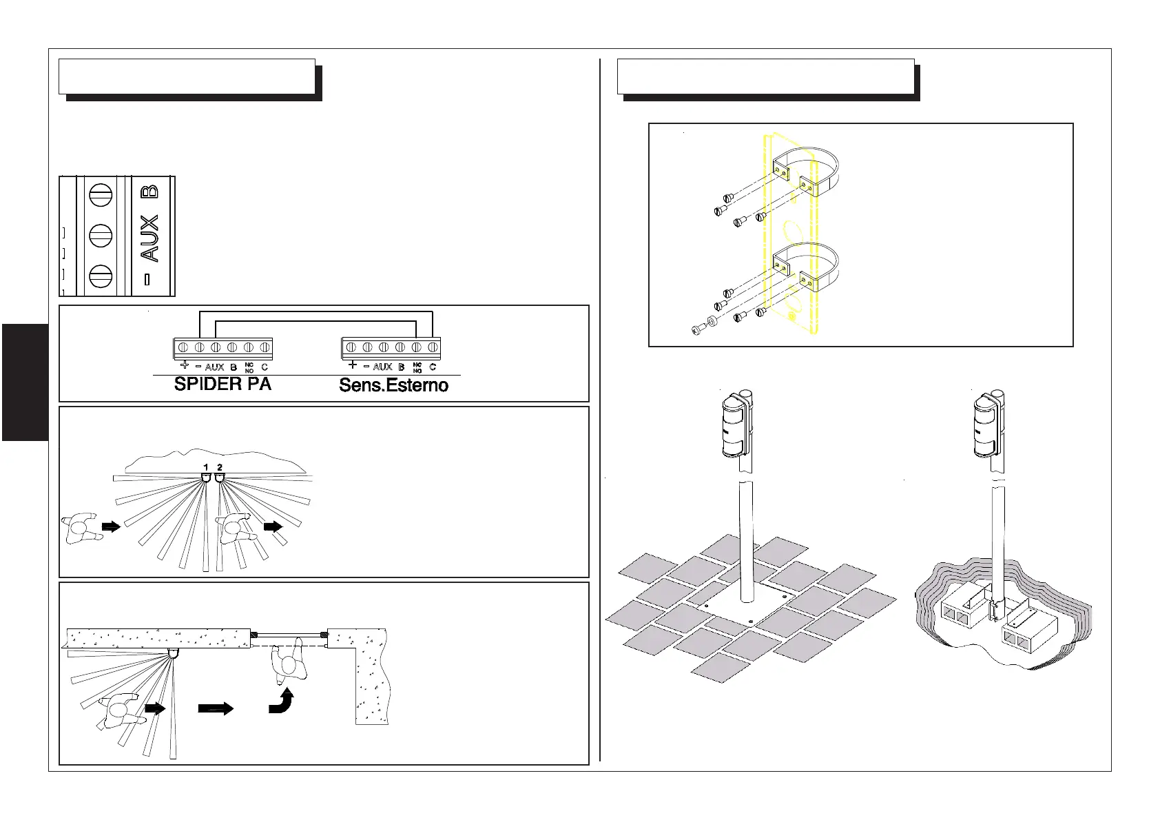
Using the AUX input, it is possible to set SPIDER PA to operate in AND o
DIRECTIONAL AND combination with another detector.
To activate the AND mode, look at pag.9 (DIP 3).
The input AUX must be closed to negative, when the
second detector is not in alarm.
CONNECTION EXAMPLE
Floor standing bracket mod.
SB120
Burried bracket
mod. SB130
Cross before the
detection area of
SPIDER PA and then
SILVER in 30 second,
as shown, to produce
alarm signal.
2° Example of DIRECTIONAL AND installation:
SPIDER PA and an active barrier SILVER in DIRECTIONAL AND
Cross the detection area in 30
second, as shown, to produce an
alarm signal.
(SPIDER1-DIP3 ON)
1° Example of DIRECTIONAL AND installation:
Two SPIDER PA in DIRECTIONAL AND