HS35A 1
HS35A PART NUMBERS AND AVAILABLE OPTIONS
Model PPR
Line
Driver
Bore Options Connector Options
Mounting
Style
Protection
Anti-Rotation
Tether Options
Channels
Special
Features
HS35A
1-
5-28V
(7272)
2-
5-28V,
open
collector
(7273)
4-
5-28V in,
5V out
(7272)
W-
18" flex. cable
Y-
18” flex. cable BEI
wire colors
U-
Universal
End-of-Shaft
& Thru Shaft
0-
None
1-
Basket
X- None
A- Fan cover, 1/4-20
B- Fan cover, 5/16-18
C- Fan cover, 3/8-16
D- Fan cover, all
E- 4.5" or 6.75" C-Face
F- 8.5" C-Face
M- 4.5" C-Face or Fan
Cover
R- Pin and block
U- Universal
(all tether options)
A-
A,A
–
,B,B
–
,
Z,Z
–
B-
A,A
–
,B,B
–
«
D-
A,A
–
«
E-
A,B,Z
«
F-
A,B
«
000-
None
9xx-
Specify
cable length
xx=feet (use w/
option “W”)
00W-
Connector
on cable
DESCRIPTION
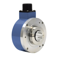
The Avtron Model HS35A Hollow Shaft Rotary Incremental Encoder is a
speed and position incremental transducer (also known as tachometer
or rotary pulse generator). When mounted to a motor or machine, its
output is directly proportional to shaft position (pulse count) or speed
(pulse rate). The HS35A operates down to zero speed and can be used
for both control and instrumentation applications.
The HS35A employs a hollow shaft and clamping collar to lock the
encoder to the shaft. A high-performance resin hollow shaft insert
provides electrical isolation from motor shaft currents and permits
models to fit a broad range of shaft sizes from 1/2" to 1" [12mm -
20mm]. An anti-rotation bracket prevents rotation of the encoder while
allowing for shaft end float and axial movement. An optional protective
basket kit offers additional protection from impact and motor lifting
damage.The HS35A encoder offers 2Ø outputs (A,B) 90° apart for
direction sensing (A Quad B), with complements (A,B) and with
marker pulse and complement (Z,Z)
.
INSTALLATION CONSIDERATIONS
See page 3 and drawing on last page for shaft engagement rules.
Shaft may include keyway, but should not be flatted.
The HS35A offers optional Avtron flexible anti-rotation tethers/
brackets which will permit the encoder to tolerate ±0.1" of shaft end
float/axial movement. Select the proper tether for the application from
the table below.
CAUTION
Be careful not to damage clamping fingers of hollow
shaft during handling. Do not tighten clamping collar
before installation onto motor shaft.
8901 E. PLEASANT VALLEY ROAD
•
INDEPENDENCE, OHIO 44131-5508
TELEPHONE: (1) 216-642-1230
•
FAX: (1) 216-642-6037
E-MAIL: tachs@nidec-avtron.com
•
WEB: www.avtronencoders.com
Nidec-Avtron Makes the Most Reliable Encoders in the World
Encoder
Instructions
HS35A
1/2" to 1" [12mm-25mm]
HOLLOW SHAFT
WARNING
Installation should be performed only by qualified
personnel. Safety precautions must be taken to ensure
machinery cannot rotate and all sources of power are
removed during
installation.
WARNING
Be certain to identify thread locker and anti-seize
compound correctly. Using anti-seize in place of
thread locker can cause mechanical failure leading to
equipment failure,
damage, and harm to operators.
Equipment Needed for Installation
Provided Optional Not Provided
HS35A Encoder
Clamping Collar
Anti-Rotation
Tether Kit
Shaft Sizing Insert
Mating MS Cable
Connector
Protective Basket Kit
#2 Phillips Screwdriver
5/32" Hex Wrench (US)
3mm Hex Wrench (Metric)
(T-Handle Style)
Caliper Gauge
Dial Indicator Gauge
7/16", 9/16", 5/8", 3/4", 10mm
Wrenches (tether options)
All dimensions are in inches [millimeters].
Specifications and features are subject to
change without notice.
*Requires option code “00W”
G- 100
K- 200
L- 240
M- 250
Q- 500
R- 512
S- 600
W- 1000
Y- 1024
Z- 1200
3- 2000
4- 2048
5- 2500
8- 4000
D- 4096
9- 5000
0-
Special
«
Only available with MS 6 and 7 pin connectors
Connector Options
10 Pin MS 6 Pin MS 7 Pin MS 8 Pin M12 10 Pin Mini-twist lock*
A-
w/o plug (std. phasing)
B-
w/o plug (Dynapar
HS35 phasing)
C- “A”
w/ plug
D- “B”
w/ plug
E-
w/o plug (std. phasing)
F-
w/o plug (Dynapar
HS35 phasing)
G- “E”
w/ plug
H- “F”
w/ plug
J-
w/o plug (std. phasing)
K-
w/o plug (Dynapar
HS35 phasing)
M- “J”
w/ plug
N- “K”
w/ plug
T-
w/o plug (Turck Pinout)
U-
w/o plug (US Pinout)
R- 10 pin mini twist lock
w/o plug (bulkhead)
S- 10 pin mini twist lock
on cable*
0-
Non-std.
B-
1/2
C-
5/8”
D-
3/4”
E-
7/8”
F-
1”
P
- 12mm
Q
- 14mm
R
- 15mm
S
- 16mm
V
- 19mm
W
- 20mm
Y
- 25mm
U-
Universal 1/2” to
7/8” (all U.S. inserts)
Z-
Universal 12mm to
20mm (all metric inserts)