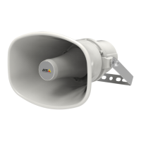
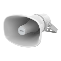
AXISC1310-ENetworkHornSpeaker
Specifications
Buttons
Controlbutton
Thecontrolbuttonisusedfor:
•Calibratingthespeakertest.Pressandreleasethecontrolbuttonandatesttoneisplayed.
•Resettingtheproducttofactorydefaultsettings.SeeResettofactorydefaultsettingsonpage33.
Microphonedisableswitch
Forlocationofthemicrophonedisableswitch,seeProductoverviewonpage36.
ThemicrophonedisableswitchisusedtomechanicallyturnthemicrophoneONorOFF.Thefactorydefaultsettingforthisswitch
isON.
Connectors
Protectiveearthterminal
DANGER
Riskofelectricshock.Theproductshallbegroundedusingagroundingwire.Makesurebothendsofthegroundingwire
areincontactwiththeirrespectivegroundingsurfaces.
Makesurethegroundingwireisasshortaspossibletomakethecurrentpathasshortaspossible.
Networkconnector
RJ45EthernetconnectorwithPoweroverEthernet(PoE).
NO NO
NO
TICE TICE
TICE
Theproductshallbeconnectedusingashieldednetworkcable(STP).Allcablesconnectingtheproducttothenetworkshall
beintendedfortheirspecicuse.Makesurethatthenetworkdevicesareinstalledinaccordancewiththemanufacturer’s
instructions.Forinformationaboutregulatoryrequirements,seetheInstallationGuideatwww.axis.com.
I/Oconnector
UsetheI/Oconnectorwithexternaldevicesincombinationwith,forexample,motiondetection,eventtriggering,andalarm
notications.Inadditiontothe0VDCreferencepointandpower(DCoutput),theI/Oconnectorprovidestheinterfaceto:
Digitalinput-Forconnectingdevicesthatcantogglebetweenanopenandclosedcircuit,forexamplePIRsensors,door/window
contacts,andglassbreakdetectors.
Digitaloutput-ForconnectingexternaldevicessuchasrelaysandLEDs.ConnecteddevicescanbeactivatedbytheVAPIX®
ApplicationProgrammingInterface,troughaneventorfromtheproduct’swebpage.
4-pinterminalblock
FunctionPinNotes
Specications
DCground
1
0VDC
37