EasyManua.ls Logo

Axminster SIEG X1 Super Micro Mill Mk2 User Manual

Axminster SIEG X1 Super Micro Mill Mk2
24 pages
To Next Page IconTo Next Page
Page #1 background imageLoading...
Page #1 background image
2004
600881
SIEG X1 Super Micro
Mill Mk2
Axminster Reference No:X1
Mk2 Part No: 600881
User Manual
WHITE
AXMINSTER
W
www.axminster.co.uk
Question and Answer IconNeed help?

Do you have a question about the Axminster SIEG X1 Super Micro Mill Mk2 and is the answer not in the manual?

Axminster SIEG X1 Super Micro Mill Mk2 Specifications

General IconGeneral
BrandAxminster
ModelSIEG X1 Super Micro Mill Mk2
CategoryTools
LanguageEnglish

Summary

Declaration of Conformity

General Instructions for 240v Machines

Good Working Practices/Safety

Essential safety practices for operating machinery.

Primary Precautions

Key safety measures before using mains powered tools.

Work Place/Environment

Guidelines for a safe and suitable operating area.

Initial Assembly and Testing

Testing

Step-by-step verification of machine functionality after assembly.

Specifications

Definitions

'X' Axis

Defines side-to-side movement of the worktable.

'Y' Axis

Defines front-to-back movement of the worktable.

'Z' Axis

Defines vertical movement of the spindle/head.

Parts Identification and Description

Base casting

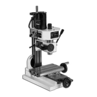
The main stand supporting the milling machine.

Main tool post

The column that supports the milling head.

Rise and fall drive screw

Mechanism for adjusting the head's vertical position.

Tilt housing

Component allowing the main tool post to tilt.

Traverse slide

Mounts on the base, moves the worktable side-to-side.

Traverse slide control

Handle for operating the traverse slide.

Machine Illustration of the Micro-Mill

Parts Identification and Description (Continued)

Worktable

The surface where workpieces are mounted.

Worktable drive control

Handle for moving the worktable.

Milling head

The main part housing the spindle and motor.

Milling head casting

The primary structure of the milling head.

Head clamp and scale

Secures the head and indicates tilt angle.

Rise and fall drive screw dog

Connects rise/fall screw to the head casting.

Motor and gearbox

Houses the motor and transmission for spindle drive.

Gear change knob

Selects speed ratios for the spindle.

Motor

Provides power for the spindle drive.

Feed Handle

Controls the quill's up and down movement.

Machine Illustration of the Micro-Mill (Continued)

Parts Identification and Description (Continued)

Fine feed assembly

Mechanism for precise quill movement.

Motor control panel

Interface for power and speed control.

Fuse Cap

Access point for the motor fuse.

Forward /Off/Reverse Switch

Controls spindle rotation direction.

Quill hold pocket

Feature for securing the quill during tool changes.

Draw bar cover

Protects the top of the draw bar.

Draw bar (unseen)

Secures tools in the spindle taper.

Machine Illustration of the Micro-Mill (Continued)

Machine Illustration of the Micro-Mill (Continued)

General Operating Instructions

Tool Changing

Procedure for replacing cutting tools or chucks.

General Safety Points

Critical safety considerations during operation.

Settings and adjustments

Feed scales

How to use and adjust measurement thimbles on feed handles.

Worktable and Traverse feed adjustment

Adjusting gib strips for smooth table movement.

Milling Head adjustment

Adjusting gib strips for smooth head movement.

Maintenance

Daily and Periodic Maintenance

Recommended schedule for cleaning and lubrication.

Accessories

Information on available optional equipment.

Illustrated Parts Breakdown of the Micro-Mill Part 1

Illustrated Parts Breakdown of the Micro-Mill Part 2

Illustrated Parts Catalogue of the Micro-Mill Part 1

Illustrated Parts Catalogue of the Micro-Mill Part 2

Micro-Mill Accessories

Micro Mill Oiling Points

Related product manuals