Do you have a question about the Aybey Elektronik AE-LIFT Series and is the answer not in the manual?
| Cooling Method | Forced air cooling |
|---|---|
| Storage Temperature | -20°C to +60°C |
| Control Method | Vector Control |
| Protection Features | Overvoltage, Undervoltage, Overcurrent, Short Circuit, Overheating |
| Application | Elevators |
| Communication | Modbus |
| Operating Temperature | -10°C to +40°C |
| Humidity | Less than 95% RH, non-condensing |
| Altitude | Up to 1000m (derating above 1000m) |
Technical specifications for electrical components and capacities of the AE-Lift motor driver.
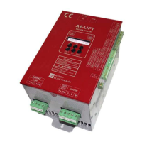
Details the physical dimensions and mounting information for the AE-Lift motor driver box.
Describes the primary power and control circuit connections for the AE-Lift motor driver.
Details how to connect the AE-Lift motor driver to induction and synchronous (gearless) motors.
Explains the methods for controlling motor contactors, either directly by the AE-Lift or via a control panel.
Details how the AE-Lift directly controls motor contactors for accurate timing and release.
Describes control panel-based contactor switching, emphasizing the role of the REN relay for safety.
Provides the connection diagram and advice for switching the brake coil in the AE-Lift system.
Lists and defines the terminals for the power circuit of the AE-Lift motor driver.
Details input and output terminals for the control circuit of the AE-Lift motor driver.
Lists terminals for encoder connections, crucial for closed-loop control.
Details incremental encoder terminal connections for asynchronous motors.
Explains encoder board requirements and terminal lists for synchronous (gearless) motors.
Describes the functions of the keypad buttons for parameter adjustment and system observation.
Explains the meaning and behavior of the yellow (ERROR) and green (STATUS) warning LEDs.
Details how information like startup, main screen, version, serial number, and I/O status is displayed on the LCD.
Covers parameters related to adjusting the lift's speed settings, including selection and acceleration/deceleration.
Details parameters for selecting and configuring different speed levels for the lift.
Explains how speed inputs are enabled and how they function based on parameter settings.
Defines the order of priority for active speed inputs when multiple are active.
Lists and describes parameters for qualifying various speed settings like creeping, inspection, and rescue speeds.
Details parameters controlling the rate at which the lift accelerates to its target speed.
Explains the [S10] parameter for setting the system's acceleration value.
Describes how S-curve parameters ([S11], [S12]) provide smooth acceleration transitions.
Covers parameters that manage the rate at which the lift slows down.
Explains the [S13] parameter for setting the system's deceleration value.
Details how S-curve parameters ([S14], [S15]) provide smooth deceleration transitions.
Explains parameters ([S17], [S18]) related to the lift's stopping behavior and reference speed.
Covers all timing parameters essential for comfortable drive and stopping processes.
Details timing parameters related to the startup sequence of the lift system.
Explains timing parameters that govern the stopping sequence and brake release.
Parameters for controlling the lift's operation beyond speed and timing.
Covers general control parameters like drive type, encoder filter, and carrier frequency.
Explains the Proportional-Integral-Derivative control system for motor speed adjustment.
Details PD control coefficients ([C03], [C04]) for managing slip during zero speed startup.
Explains PI control coefficients ([C05], [C06]) for motion and start speed adjustments.
Describes PI coefficients for motion control, varying based on speed ranges.
Covers voltage/frequency (V/f) curve control for lift operations without encoder feedback.
Details how the AE-Lift driver handles rescue operations using battery or UPS during power failures.
Parameters related to motor and encoder specifications, set by user or tuning process.
Explains the functions of three programmable inputs (I1, I2, I3) for custom control actions.
Details the two programmable outputs (O1, O2) and their associated functions.
Describes the menu password protection feature and how to change the password.
Guides through the motor tuning process for defining motor parameters without requiring motor rotation.
How to access and interpret saved error logs for troubleshooting the AE-Lift system.
Displays the screen for accessing the error log from the main menu.
Shows the format of the error log list, including sequence and error codes.
Provides detailed error information, including target speed and motion mode.
Displays further error details such as reference speed, output current, and bus voltage.
Explains how to connect the AE-Lift driver to a computer via Ethernet for parameter management and monitoring.
