Appendix A: Specifications
A-9
Model Number Configuration
Azbil CorporationNo. SS2-AVP300-0100
6
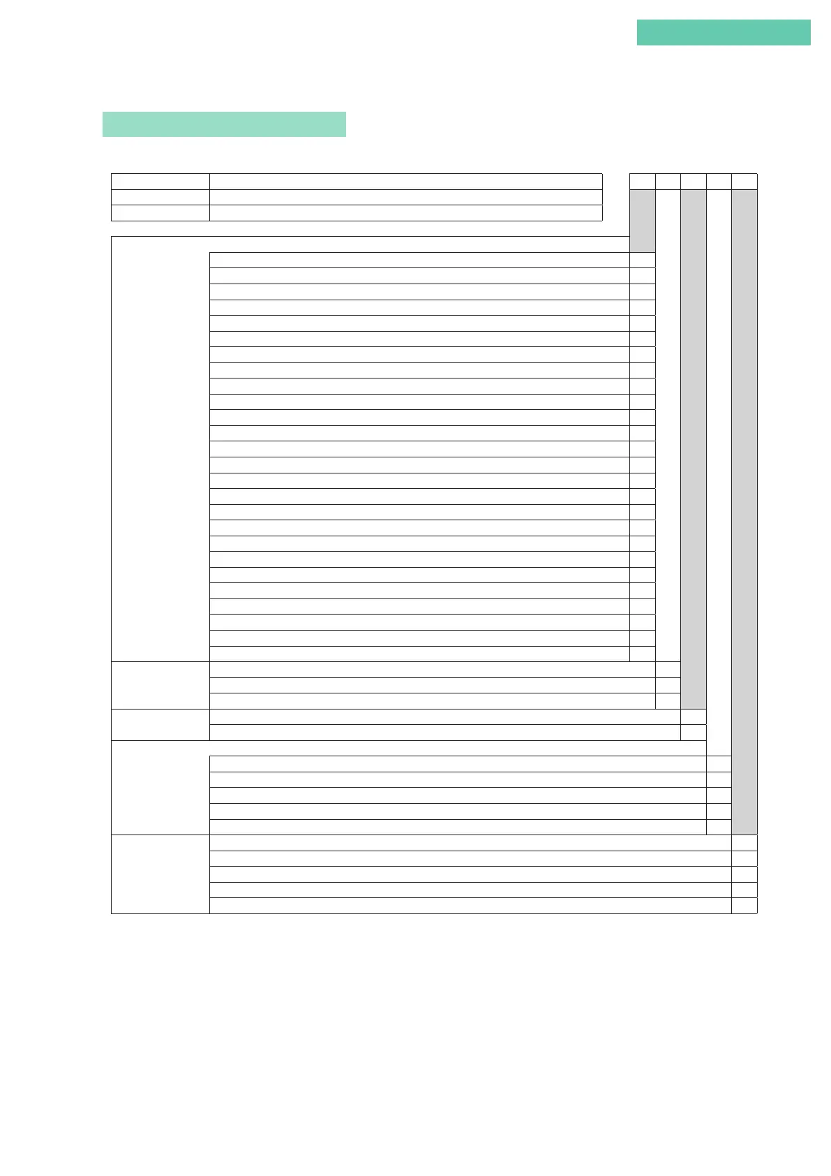
MODEL SELECTION
Basic model number
AVP300 Analog signal (4 to 20 mA DC) without position transmission
-
(1) (2) (3) (4) (5)
AVP301 Analog signal (4 to 20 mA DC) with position transmission
AVP302 Analog signal (4 to 20 mA DC) HART
®
protocol
(Air pipes, conduit connections)
(1) Main unit model
number
Water-proof (Rc1/4, G1/2)
X
Water-proof (1/4 NPT, 1/2 NPT)
P
Water-proof (1/4 NPT, M20×1.5)
Q
TIIS Flameproof with cable gland
*1
(Rc1/4, G1/2)
E
KOSHA Flameproof (Rc1/4, G1/2)
S
KOSHA Flameproof (1/4 NPT, 1/2 NPT)
H
FM Explosionproof and Flameproof (1/4 NPT, 1/2 NPT)
F
FM Intrinsically safe (1/4 NPT, 1/2 NPT)
M
FM Intrinsically safe (1/4NPT,G1/2)
6
ATEX Flameproof (1/4 NPT, M20×1.5)
C
ATEX Flameproof (1/4NPT,1/2NPT)
Y
ATEX Intrinsically safe (Model AVP301 not available) (1/4 NPT, M20×1.5)
L
ATEX Intrinsically safe (Model AVP301 not available) (1/4NPT,1/2NPT)
U
ATEX Intrinsically safe (Model AVP301 not available) (1/4NPT,G1/2)
V
NEPSI Flameproof (1/4 NPT, 1/2 NPT)
B
NEPSI Flameproof (1/4 NPT, M20×1.5)
N
NEPSI Intrinsically safe and Flameproof (1/4 NPT, 1/2 NPT)
R
NEPSI Intrinsically safe and Flameproof (1/4 NPT, M20×1.5)
W
IECEx Flameproof (1/4 NPT, 1/2 NPT)
J
IECEx Flameproof (1/4 NPT, M20×1.5)
G
INMETRO Flameproof (1/4 NPT, 1/2 NPT)
3
INMETRO Flameproof (1/4 NPT, M20×1.5)
2
EAC Flameproof (1/4 NPT, M20×1.5)
7
EAC Intrinsically safe (1/4 NPT, M20×1.5)
8
CNS Flameproof (1/4 NPT, 1/2 NPT)
D
CNS Flameproof (1/4 NPT, M20×1.5)
1
(2) Finish
Standard (Baked Acylic)
S
Corrosion proof (Baked polyurethane)
B
Silver finish (Baked Acrylic)
D
(3) Positioner action
* 2
Direct Action (standard) - Air pressure increases with Control signal increase
D
Reverse Action (reverse positioning) Airpressure decreases with Control signal increase
R
(Pressure gauge scale, Max regulator setting)
(4) Supply air pressure
type
140 ≤ Ps ≤ 150 kPa (200 kPa, 400 kPa)
1
150 < Ps ≤ 300 kPa (400 kPa, 400 kPa)
2
300 < Ps ≤ 400 kPa (600 kPa, 400 kPa)
3
400 < Ps ≤ 450 kPa (600 kPa, 700 kPa)
4
450 < Ps ≤ 700 kPa (1000 kPa, 700 kPa)
5
(5) Pressure units
kPa
A
(kgf/cm
2
)
* 3
(B)
MPa
C
bar
D
(psi)
*3
(E)
*1. Model AVP300/302 includes one flameproof cable gland, and model AVP301 includes two.
*2.
When the input signal (power) is shut off, select direct action to make the output air pressure of this device zero, and reverse action to make
the output at the maximum air pressure (supply air pressure). Positioner action differs from actuator and control valve action, so be careful
in selecting the positioner’s action.
*3. Items in parentheses are for overseas use. As such, they cannot be used in Japan.
 Loading...
