A-10
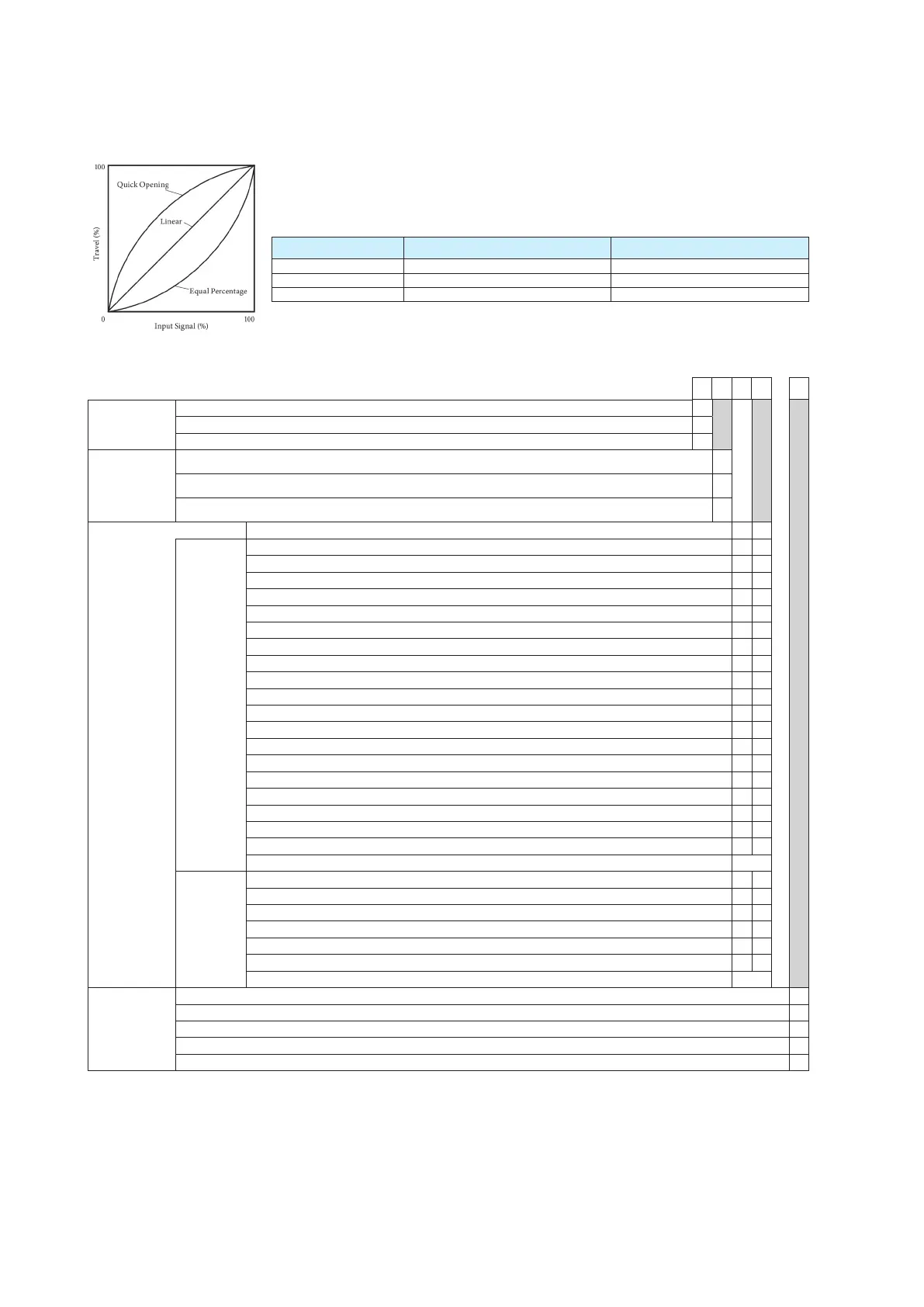
Figure 1. Input-output
characterization
Selection of input characterization
The flow characteristic of a control valve is set by selecting the valve plug characteristic, and the input-output
characteristics of the positioner must be specified as linear. However, if the valve plug flow characteristic, which
depends on the control valve’s shape and structure, does not meet requirements, you can correct the overall flow
characteristic of the control valve by specifying “equal percentage” or “quick opening” for the input-output charac-
teristics of the positioner, as shown in Table 1.
Table 1. Control valve flow characteristics correction by the positioner
Characteristic of valve plug Input-output characterization of positioner Overall flow characteristic of control valve
Linear Quick opening Quick opening
Linear EQ% EQ%
EQ% Quick opening Linear
Note: If the valve plug characteristic is “quick opening,” the overall ow characteristic of the control valve cannot be
linear even if “equal percentage” is set for the positioner’s input-output characteristics. (is is because when
the valve plug characteristic is “quick opening,” the control valve works as an ON/OFF valve and it is dicult to
correct its characteristics by changing the setting of the positioner.)
Accessory Selection
(6) (7) (8) (9) -
(10)
(1) Regulator
with filter
Without regulator X
With model KZ03 regulator (attached to main unit) 1
With model KZ03 regulator (with mounting plate for separate installation) 2
(2) Mounting
bracket
material
(mounting
plate/bolts)
No mounting plate X
SS400 standard zinc-plating / SUS304 C
SUS304 / SUS304 D
(8) (9)
Mounting
bracket for
attachment to
actuator*
7
No mounting plate X X
Single-acting
actuators
PSA1, PSA2, PSK1 Y S
New model of PSA3, PSA4/VA1 to VA3 produced aer 2000*
4
Y Q
PSA3, PSA4 for existing valves produced on/before 1999 Y Y
PSA6/VA4 to VA6 produced aer Apr.’83*
4
Y L
PSA7 Y 8
HA1 Y A
HA2, HA3, HL2, HL3 Y T
HA4, HL4 Y N
HK1, VM1*
5
Y K
VM12 for model VSP*
6
Y B
VR1 Y V
VR2, VR3 Y R
VR3H Y 6
RSA1 Y F
RSA2 Y U
GOM 83S, GOM 84S, GOM 103S Y G
GOM 124S Y M
VA1 - VA3 (for old-model motion connectors) Produced on/before Apr.‘83 800-1, 800-3*
8
Y W
VA4 - VA5 (for old-model motion connectors) Produced on/before Apr.‘83 800-4, 800-5*
8
Y J
Actuators of other manufacturers
See Table 2
Double-
acting
actuators
VP5, 6 *
9
Y 1
VP7 *
9
Y 7
SLOP560, 1000, 1000X *
9
*
10
Y 2
SLOP1500, 1500X *
9
*
10
Y 3
DAP560, 1000, 1000X *
9
*
10
Y 4
DAP1500, 1500X *
9
*
10
Y 5
Actuators of other manufacturers
See Table 3
(10) Option
None X
Explosion-proof universal elbow (SUS304 G1/2) (1) A
Explosion-proof universal elbow (SUS304 G1/2) (2) C
Mounting screw Unify (5/16-18UNC) (Electrical conduit connection only supports 1/2NPT) T
Double-acting reversing relay W
*4. Select “YW” or “YJ” for old-type motion connectors. (Produced on/before Apr.’83)
*5. In case “VM” type actuator is required following conditions, 1. select model “VCT” for the body, 2. the existing positioner should be HEP or VPE, 3. yoke
should be model HK. If another spec. is required, contact your sales representative.
*6. Additional support bracket is required.
*7. Accuracy diers depending on the actuator’s stroke; see Table 1.
*8. Consult with sales representative in case of no mounting hole on the side of valve yoke.
*9. In case of double acting actuator, a reversing relay unit required.
*10. Contact a sales representative if a bracket for model VFR (FloWing) or buttery valve is required.
 Loading...
