12
AB-7521
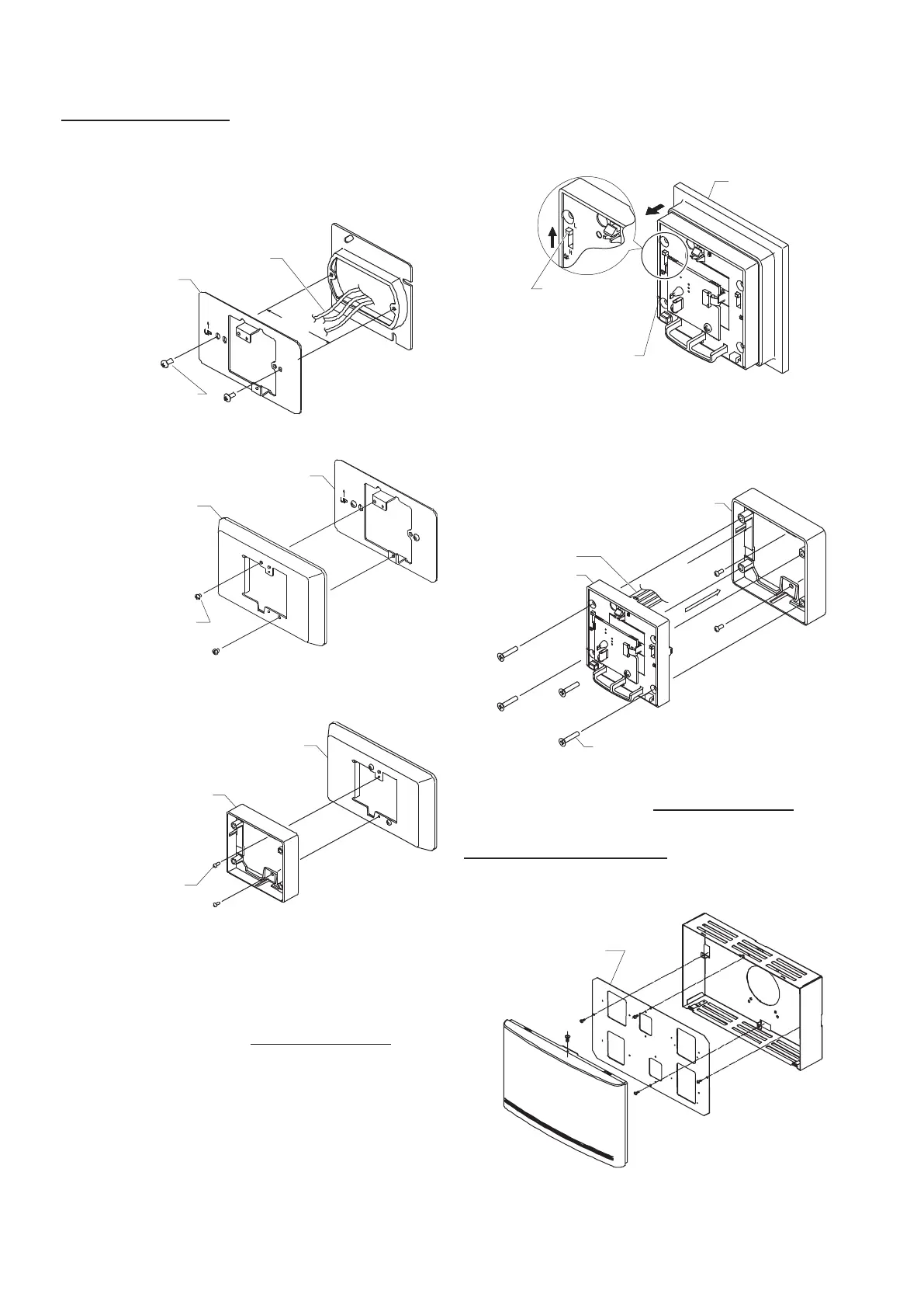
Thermoplate mounting
(1) Attach the mounting plate of Thermoplate to the
outlet box cover (JIS C8340:1999, mounting
dimension for switch box 83.5 mm) on the
mounting surface.
83.5mm
Mounting box cover
JIS C8340, mounting
dimension 83.5 mm
Wires from the load
Mounting plate
2 pan-head screws
(M4, L = 8)
(2) Attach the Thermoplate to the mounting plate.
Mounting plate
Thermoplate
2 pan-head screws
(M4, L = 8)
(3) Attach the main unit of the Thermoplate
mounting kit to the Thermoplate.
Thermoplate
Main unit of
Thermoplate
mounting kit
2 tapping screws
(M2.6, L = 8)
(4) Connect the lead wires of the main unit and the
wires from the load.
Refer to Figs. 17 and 18 in ■ “Wiring.”
(5) Detach the cover of the main unit.
Refer to step (4) in Wall-direct mounting.
(6) Set the depth change levers on the both sides
of the main unit to the upper position (indicated
with "L") .
Wall-direct
mounting kit
Main unit
Depth change levers
(located at the upper
position, indicated
with "L")
(7) Attach the main unit to the Thermoplate
mounting kit.
Use the 4 screws (M3, flat-head, L = 16)
supplied with the sensor.
4 flat-head screws (M3, L = 16)
Main unit
Main unit of Thermoplate mounting kit
(8) Attach the cover back to the main unit.
Refer to step (7) in Wall-direct mounting.
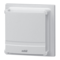
Multi-thermocase mounting
When attached to the Multi-thermocase, remove
the cover of the main unit.
Mounting plate of
Multi-thermocase
Figure 9. Multi-thermocase
 Loading...