Do you have a question about the B-52 US-1200 and is the answer not in the manual?
Guidance on safely unpacking and setting up the amplifier, including placement and environmental precautions.
Explanation of electrical hazard and important instruction symbols used in the manual for user safety.
Essential safety guidelines for amplifier operation, including water avoidance, proper ventilation, and cord protection.
Measures for safe usage concerning water, heat, power sources, grounding, and cleaning procedures.
Guidelines for safe servicing, using specified replacement parts, and post-repair safety checks.
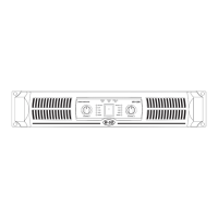
Overview of features like compact size, rugged build, high-current transformers, gain controls, and selectable modes.
Details on securing the amplifier in a rack and maintaining airflow through vents and filters.
Explanation of gain controls and green LEDs indicating signal presence and attenuation levels.
Description of red CLIP LEDs for distortion and yellow PROTECT LEDs for protection modes.
Explanation of GREEN LEDs for BRIDGE/PARALLEL modes and the BLUE POWER LED status.
Location and operation of the main power switch for turning the amplifier on and off.
Information on cooling fans and balanced/unbalanced input connectors (XLR, 1/4" TRS) and link connectors.
Details on the slide switches for the built-in High Pass filters to roll off signals below 50Hz.
Explanation of the limiter switch (US-3000/4000) and the mode switch for STEREO, PARALLEL, BRIDGED.
Guidance on using binding posts for speaker connections, including essential impedance warnings.
Instructions for using Speakon connectors for speaker output, including BRIDGE mode configuration.
Mandatory warnings about minimum impedance requirements for STEREO, PARALLEL, and BRIDGED modes.
Details on the circuit breaker reset function and the importance of the AC input's earth pin connection.
Explanation of protection during power-up and thermal protection engaging due to overheating heatsinks.
Guidance on checking speaker impedance and air filters when thermal protection is repeatedly triggered.
Protection against DC voltage at speaker outputs and built-in subsonic filters for enhanced audio.
Explanation of circuitry protecting against excessive current and output short circuits.
Details on how clip limiters prevent distortion, their operation, and recommended settings for optimal performance.
Guidance on using HPF to optimize bass response and speaker performance, with recommended settings.
Explanation of independent channel operation in STEREO and signal distribution in PARALLEL mode.
Details on combining channels for higher power, including impedance warnings and connection specifics.
Diagrams illustrating speaker connections for STEREO and PARALLEL modes using binding posts.
Diagrams showing speaker connections for BRIDGED MONO mode using binding posts.
Visual guides for wiring speakers in STEREO mode using Speakon and binding posts.
Visual guides for wiring speakers in PARALLEL mode using Speakon and binding posts.
Visual guides for wiring speakers in BRIDGED MONO mode using Speakon and binding posts.
Explanation of XLR input/output pin assignments for balanced and unbalanced signals.
Details on wiring for unbalanced and balanced 1/4" connectors, including bridging for unbalanced.
Diagrams and explanation of Speakon connector pinouts for front and rear views.
Details the 3-year warranty, coverage, exclusions, and remedies for US-Series amplifiers.
Instructions for product returns, obtaining a RAN, and contacting customer service for support.
| Type | Power Amplifier |
|---|---|
| Number of Channels | 2 |
| Frequency Response | 20Hz - 20kHz |
| THD | <0.1% |
| S/N Ratio | >100dB |
| Bridged Power (8 ohms) | 1200W |
| Input Impedance | 10k Ohm Unbalanced, 20k Ohm Balanced |
| Power Output (2 ohms) | 600W RMS per channel |
| Power Output (4 ohms) | 400W RMS per channel |