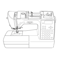
Do you have a question about the Baby Lock Triumph BLETS8 and is the answer not in the manual?
Identifies ELx705CF needle system, compatible models, and plating.
Identifies HAx1SP/CR needle system, compatible models, and plating.
Identifies HAx1 (130/705H) needle system for household machines and plating.
Details adjustment of the lower looper for optimal sewing performance.
Provides instructions for adjusting the chain looper mechanism.
Specifies the correct height setting for the sewing needle.
Outlines the procedure for adjusting the presser foot height.
Details the process for adjusting the upper looper.
Describes how to set the clearance between the upper and lower loopers.
Step-by-step guide for replacing the lower looper component.
Instructions on setting the correct position for the lower looper.
Details on adjusting the distance between the lower looper and needle.
Steps for replacing the upper looper.
How to adjust the upper looper to its correct position.
Adjusting the relative positions of lower and upper loopers.
Setting the correct distance between upper and lower loopers.
Ensuring proper clearance between the upper looper and needles.
Adjusting the position of the chain looper.
Guide to adjusting the chain needle guards for proper function.
Instructions for adjusting the height of the feed dogs.
How to adjust the front-to-back position of the feed dogs.
Steps for replacing the upper knife on the machine.
Steps for replacing the lower knife on the machine.
Procedure for cutting fabric to measure cutting width.
Adjusting the cutting width using the current system.
Adjusting the stitch width dial for proper cutting alignment.
Adjusting guides and holders for smooth movement of joint pipes.
Ensuring joint pipes are centered in their receivers.
Adjusting the vertical position of joint pipes.
Adjusting the horizontal position of joint pipes.
Guide for replacing upper looper threading pipe and joint pipe.
Guide for replacing lower looper threading pipe and joint pipe.
Guide for replacing chain looper threading pipe and joint pipe.
Instructions for removing the spool stand cover.
Steps to remove the machine's belt cover.
Guide for removing the arm cover of the sewing machine.
How to remove the cover for the lower threading lever.
Instructions for removing the rear exterior cover.
Steps to remove the bed cover of the sewing machine.
Guide for removing the front exterior cover.
How to remove the cover for the thread take-up mechanism.
Instructions for removing the thread take-up guide.
Steps to remove the wave selector knob.
Guide for safely disconnecting and removing cables.
How to remove the rubber cushioning feet.
Instructions for removing the fine tuning knob.
Steps to disconnect and remove the arm cover's safety cable.
Instructions for removing the screws of the knife cover hinge.
Steps to remove the screw securing the knife holder cover.
Attaching the knife holder cover correctly.
Reattaching various parts and screws to the machine.
Reattaching the knife cover hinge.
Verifying that covers are fitted without gaps.
Setting the stitch width to its minimum for reassembly.
Ensuring safety code positions are correct during attachment.
Connecting the safety device connector properly.
Attaching the base plate, ensuring protrusions fit.
Reattaching the machine's rubber cushioning feet.
Connecting the speed controller cable.
Attaching the machine's face cover.
Reattaching the cover for the thread take-up mechanism.
Reattaching the wave selector knob.
Attaching the rear exterior cover and its screws.
Securing the rear cover using the set screw from the front.
Attaching the belt cover (first mention).
Attaching the belt cover (second mention).
Attaching the spool stand assembly.
Reattaching the front cover and its E ring.
Attaching the pressure adjusting dial, noting direction.
Reattaching the arm cover.
Identifies the main sewing motor and its connections.
Identifies the Power Printed Circuit Board and its connections.
Identifies the air threading motor and its connections.
Identifies the Control Printed Circuit Board and its connections.
Identifies the switching power supply unit.
Identifies the right-side LED indicator.
Identifies the sewing speed controller.
Identifies the button for thread loopers.
Shows connection point for the foot control pedal.
Identifies connection points on the front cover.
Identifies connection points on the side cover.
Identifies connection points for the presser foot.
Identifies the AC power input socket.
Identifies connections for needle air threading and arm cover LED.
| Brand | Baby Lock |
|---|---|
| Model | Triumph BLETS8 |
| Category | Sewing Machine |
| Language | English |
