7
ASSEMBLY INSTRUCTIONS
Hardware Used
FF
AA
1
This product contain sharp edges on
the panels
cylinder housing and
handle please install with care.
Hardware Used
2
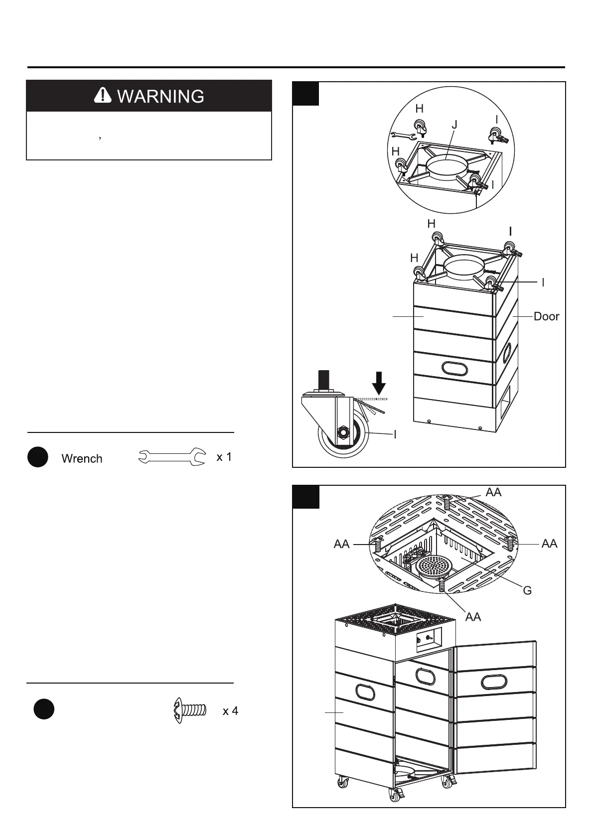
1. Turn over the product base (F) on a
non-abrasive flat surface to prevent scratching,
install the two casters (H), two casters with locking
device (I) with the base (F), gas tank support (J),
tighten them by using wrench (FF), the screw that
in gas tank supoprt is facing the door.
Note:
a. The two casters (H) are installed on two
adjacent holes on the product base (F), so are
the two casters with locking device (I).
b. The screw in the gas tank support (J) is same
direction as door in the base (F).
c. Make sure the locking device on the casters (I)
are pressed down after installation, so that the
heater will not move in any way.
2. Turn over the assembled product base, open
the door, attach burner (G) to base (F) by using
four (4) M5x15mm bolts (AA).
Note: Tighten the bolts with a Phillips screwdriver.
F
F
M5 x15mm


 To Next Page