HR-RED
High Resolution Remote Electronic Display
DSY-UM-02471-EN-01 (November 2017)
Installation Data
SCOPE OF MANUAL
This manual provides instructions for installing and using
the HR-RED (High Resolution Remote Electronic Display) .
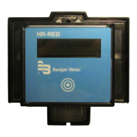
Product Description
The HR-RED is an electronic display designed to provide remote
visual readings when connected directly to Badger Meter®
Recordall® Disc, Turbo, Compound, and Fire Series meters
equipped with high resolution (HR) encoders—HR-E®, HR-E LCD,
HR-E LCD 4-20—or E-Series® Ultrasonic meters that are not easily
accessible or are in difficult to read locations. Installations such
as those inside houses or buildings, meter vaults, or dangerous
industrial locations are ideal for the HR-RED.
For additional information and product specifications, refer to the
HR-RED product data sheet, available in the Resource Library
at www.badgermeter.com.
STANDARD COMPONENTS
HR-RED Kit 64466-002
• Strain relief ring
• Three (3) connectors for wires
• Torx® seal screw
• Unit of measure adhesive label
Installation Tools
The following customer-supplied tools are recommended for installing the HR-RED. Items with a part number are available
from Badger Meter.
• Electric drill
• 3/16 in. carbide tip masonry drill bits
• Screw driver
• 59983-001 Crimping tool
• 59989-001 Cable stripper
• 59991-001 Wire cutting pliers
Wire Options (if cable supplied with the meter/encoder is not sucient)
• 64153-003 One (1) ft Belden® cable
• 68307-001 Nine (9) in. Twist Tight® connector cable
• 66488-007 Ten (10) in. Nicor® connector cable