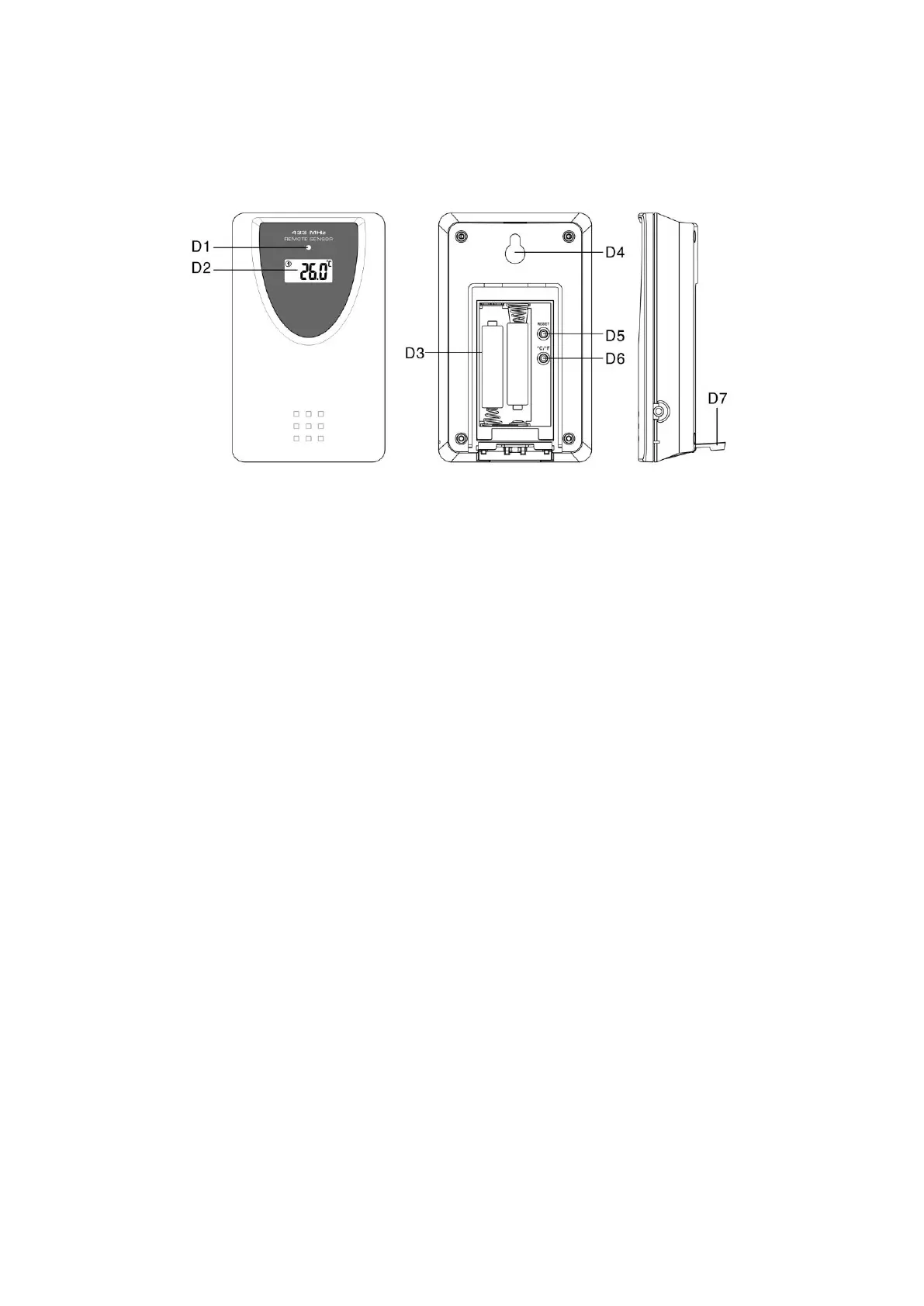
3. Outdoor Sensor Appearance.
D1: Transmission Indication LED
D2: Outdoor Temperature
D3: Battery Compartment
D4: Wall Mount Hole
D5: “RESET” button
D6: °C/°F” button
D7: Stand
4. Getting Started:
4.1 Main Unit:
Open main unit battery compartment cover [C2]
Insert 4 x AA size batteries observing polarity [ “+” and“ –“ marks]
Replace main unit battery compartment cover [C2]
Use a pin to press the RESET [B7] button on the rear of the main unit, the
main unit is now ready for use
4.2 Outdoor Thermo Sensor
Battery compartment (D3) of thermo sensor is locating behind the back cover,
unscrews the batteries cover to open.
Insert 2 x AAA batteries observing polarity [ “+” and “–“ marks]
5. Installation
5.1 Main Unit
The main unit can be placed onto any flat surface (C3), or wall mounted by
the hanging hole (C1) at the back of the unit.
5.2 Outdoor Thermo sensor