This document outlines the assembly, installation, and usage instructions for a BalanceFrom Safety Gate, designed for young children aged 6 to 24 months. The gate is available in several models, including 291338, 292385, 291433, 43348, 433527, 433575, and 575622.
Function Description:
The BalanceFrom Safety Gate serves as a barrier to prevent young children from accessing certain areas, enhancing safety within the home. It is a pressure-mounted gate, meaning it relies on tension against a doorway or opening to stay in place, rather than requiring permanent hardware installation in most cases. However, for use at the top of stairs, the manual strongly recommends the use of four wall cups for added security, indicating that in such critical locations, a more robust installation method is advised to prevent serious injury or death. The gate is designed to be expandable through the use of extensions, allowing it to fit a variety of opening widths.
Important Technical Specifications:
The gate system consists of a main Gate Frame and several optional extensions of varying widths.
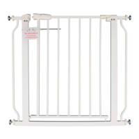
- Gate Frame (A): Included with all models, this is the core component of the safety gate.
- Threaded Spindle Rods (B): Four of these rods are included with all models. These are crucial for the pressure-mounting mechanism, allowing the gate to be adjusted and secured within an opening.
- Extensions:
- 4.72" Extension (C): Available in different quantities depending on the model: 1x for Model 291385 and 433527; 2x for Model 291433 and 433575.
- 14.17" Extension (D): Available in different quantities depending on the model: 1x for Model 43348, 433527, and 433575.
- 28.35" Extension (E): 1x for Model 575622.
- Anchor (F): Included with extensions, this component is used to secure the connection between the gate frame and any added extensions, ensuring stability across the expanded width.
The gate is intended for children aged 6 months through 24 months. It is crucial to note the warning against using the gate with a child able to climb over or dislodge it, as this could lead to serious injury or death.
Usage Features:
- Assembly and Installation:
- Step 1 (Spindle Rod Preparation): Users must rotate the adjustment bolts along the threading of the spindle rods to shrink the space between the adjustment bolt and the rubber foot. This prepares the rods for insertion and allows for later tensioning.
- Step 2 (Spindle Rod Insertion): The four prepared spindle rods are then inserted into the holes located at the four corners of the gate frame. If extensions are used, the rods are inserted into the corresponding holes on the extensions.
- Step 3 (Gate Placement and Tensioning): The gate, with or without extensions, is placed in the center of the doorway or opening. It is essential to ensure the gate is level. Once positioned, the four adjustment bolts are twisted to apply tension. The installation is considered successful when the mark line on the lock stick is approximately parallel with the lock slot opening. This visual indicator helps confirm proper tensioning.
- Extension Integration: When adding extensions, they are inserted into the gate frame or other extensions. Spindle rods are then inserted into the extension's holes. An "Anchor" component is placed at the connection point between the gate and any extension to reinforce the joint.
- Opening Mechanism: The gate features a simple opening mechanism: pull back the latch and simultaneously lift the gate. This two-step action is designed to be difficult for young children to operate.
- Safety Recommendations:
- Always read and follow all instructions carefully to ensure proper installation.
- Improper installation can lead to the gate becoming unstable or dislodged, posing a safety risk.
- For stair-top use, the four Wall Cups (not explicitly detailed in the provided pages but mentioned as recommended) should be used for secure installation. This implies that while the gate is primarily pressure-mounted, specific scenarios require additional hardware for safety.
- Never use the gate with a child capable of climbing over or dislodging it.
- Never leave a child unattended near the gate.
Maintenance Features:
- Regular Checks: Users are advised to check the gate regularly to ensure that all hardware and mountings remain tightened. This is a critical maintenance step to ensure the gate's continued safety and stability.
- Replacement Parts and Support: In case of questions or the need for replacement parts, users can contact BalanceFrom LLC directly via email (support@balancefrom.com) or phone ((310) 941-7878). The company's address is 740 Vintage Ave. Ontario, CA 91764.
- Instruction Retention: The manual emphasizes the importance of keeping the instructions for future reference, which is crucial for ongoing maintenance, troubleshooting, or re-installation.