EasyManua.ls Logo

Balboa Instruments VSP-VS510SZ-DCAH - User Manual

Default Icon
8 pages
Print Icon
To Next Page IconTo Next Page
Loading...
Page 1 54371-03_97_A
VS510SZ Tech Sheet
VS510SZ Tech Sheet
54371-03_97_A.pdf 07/11/2011
Template used: 40
6
00_P.pdf 01/07/2008
Balboa Instruments
System PN 54371-03
System Model # VSP-VS510SZ-DCAH
Software Version # 51
EPN # 3609
Base PCBA - PN 54372-03
PCB VS500Z - PN 22972 Rev C or D
Base Panels
VL700S – PN 53811
VL701S (Serial Standard) – PN 53189-01
VL702S – PN 54652
Question and Answer IconNeed help?

Do you have a question about the Balboa Instruments VSP-VS510SZ-DCAH and is the answer not in the manual?

Summary

System Revision History

Basic System Features and Functions

Power Requirements

Details electrical supply specifications like voltage, frequency, and amperage for system operation.

System Outputs

Lists the various components and devices that the system can control, including pumps, blower, ozone, and lights.

Optional Devices

Describes additional components that can be connected and used with the system, such as a circ pump.

Additional Options

Covers extra features and accessories like remote controls and specialized lighting systems.

System Memory and Power-Up

Persistent Memory Reset Procedure

Step-by-step instructions for resetting the system's persistent memory, critical for DIP switch changes.

Persistent Memory Explained

Clarifies how the system retains settings like filter cycles and temperature without a battery.

Power Up Display Sequence

Details the expected display sequence upon system power-up, including SSID and configuration indicators.

Wiring Configuration and DIP Settings

Setup 1 (As Manufactured)

Describes the default wiring configuration and component setup for the system as it is manufactured.

DIP Switch Configuration Warnings

Crucial warnings regarding power safety and persistent memory resets when adjusting DIP switches.

Panel Interface and Wiring Details

Explains panel button assignments, button positions, and provides keys for wiring color and board connectors.

DIP Switches and Jumpers Definitions

DIP Switch Key and Table

Defines the function of each DIP switch and provides a table for hi-speed pump/blower requirements.

Jumper Key and Reset Function

Explains the role of jumpers J12 and J43, particularly their use in factory settings and persistent memory resets.

Panel Button Assignments and Aux Info

Details how panel buttons are assigned to functions and provides information for auxiliary panels.

Ozone Connections

Ozone Connector Voltage Configuration

Explains how to set and change the voltage output for the ozone connector and its impact on other components.

Balboa Ozone Generator Setup

Provides guidance on correctly setting up the Balboa Ozone Generator, including wire placement for different voltages.

Ozone Connector Wiring Diagrams

Illustrates the correct wiring configurations for 120V and 240V Balboa Ozone Generator connections.

Serial Standard Panel Configurations

VL700 S Panel Configuration

Details the specific configuration and connectivity for the VL700S serial standard control panel.

VL701 S Panel Configuration

Details the specific configuration and connectivity for the VL701S serial standard control panel.

VL702 S Panel Configuration

Details the specific configuration and connectivity for the VL702S serial standard control panel.

Overview

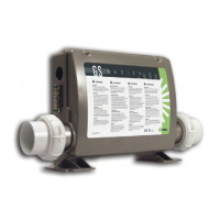
This document describes the Balboa Instruments VS510SZ spa control system, identified by System PN 54371-03. The system model is VSP-VS510SZ-DCAH, running Software Version 51, and has an EPN of 3609.

Function Description:

The VS510SZ is a spa control system designed to manage various components of a hot tub, including pumps, blowers, heaters, lights, and optional accessories like ozone generators and circulation pumps. It provides power distribution and control logic for these components, ensuring proper operation and user interaction through connected control panels. The system is designed for 240VAC, 60Hz, 40A, Class A GFCI-protected service, with a maximum circuit breaker rating of 50A. It requires a 4-wire connection (hot, hot, neutral, ground).

Important Technical Specifications:

  • System PN: 54371-03
  • System Model: VSP-VS510SZ-DCAH
  • Software Version: 51
  • EPN: 3609
  • Base PCBA: PN 54372-03
  • PCB: VS500Z, PN 22972 Rev C or D
  • Power Requirements: 240VAC, 60Hz, 40A, Class A GFCI-protected service (50A max. breaker), 4-wire connection.
  • Heater: 240V 5.5kW (rated; approximately 1.4kW at 120V).
  • Outputs (Setup 1, As Manufactured):
    • 240V Pump 1, 2-Speed
    • 240V Pump 2, 1-Speed
    • 240V Blower
    • 120V Ozone (voltage must match Circ Pump)
    • 12V Spa Light
    • 120V AV (Stereo)
  • Optional Devices: 120V Circ Pump (voltage must match Ozone).
  • Panel Compatibility: VL700S (PN 53811), VL701S (Serial Standard, PN 53189-01), VL702S (PN 54652). These panels connect to Main Board terminal J1. Panels with back-lighting should only be plugged into J1. If backlight bulbs are removed, both J1 and J2 may be used.
  • DIP Switch Settings: Configurable for various operational parameters, including test mode, amp draw requirements, off-board pump enablement, aux freeze, pump speeds, circ modes (non-circ, circ acts like pump 1 low, 24 hours with 3°F shut-off), 50Hz/60Hz operation, J17/26 equipment enablement, and temperature display units (Celsius/Fahrenheit).
  • Jumper Settings:
    • J12: Factory set, DO NOT MOVE. Must be on Pins 1 and 2 for VS51xZ/VS5xxSZ/VS5xxDZ software, or Pins 2 and 3 for VS50xZ software.
    • J43: Used for resetting Persistent Memory.

Usage Features:

  • System Revision History:
    • 54371-01 (EPN 1801, 08.09.2006): Initial release.
    • 54371-02 (EPN 2765, 04.14.2008): Software updated to v43.
    • 54371-03 (EPN 3609, 07.11.2011): Reduced poll duration from 2 minutes to 1 minute, and pump purge duration from 5 minutes to 1 minute.
  • Power Up Display Sequence: Upon power up, the display shows the SSID (System Software ID) and Software Version (e.g., 100 67 38 for VS511SZ at version 38). This is followed by "24" (for 240VAC systems with 3-6kW heater) or "12" (for 120VAC systems or GS models with 1-3kW heater). Finally, "P" appears to signal Priming Mode.
  • Persistent Memory: The system utilizes non-battery memory to store filter settings, set temperature, and heat mode.
  • Time of Day Retention: Persistent Memory does not retain Time of Day. If power is lost, the system resets to 12:00 PM. Only models with Serial Deluxe panels (VS5xxDZ and GS5xxDZ) can display the time.
  • Ozone Connector Voltage: The VS500Z board is factory configured for either 120V or 240V to the on-board ozone connector (J29). The voltage can be changed in the field by adjusting W2. This also affects the voltage supplied to the circ pump connector (J47).
  • Panel Button Assignments: Standard panels (VL700S, VL701S, VL702S) typically have buttons for Mode, Temp Up/Down, Light, Pump 1, Pump 2, and J17/26. Aux panels (VX20, VX40S) support 2 or 4 buttons for common functions.
  • Optional Accessories:
    • Dolphin Remote: Full Feature and Spa-only versions available.
    • IR Receiver Module: Connects to J1 or J2.
    • MoodEFX Lighting: Connects to Spa Light terminal J20.
    • FiberEFX Lighting: Connects to Spa Light terminal J20.

Maintenance Features:

  • Resetting Persistent Memory: Essential after changing any DIP Switch (except A1) to ensure new settings take effect.
    1. Power down the spa.
    2. Place a jumper across J43 (covering both pins).
    3. Power up the spa.
    4. Wait for "P" to display on the panel.
    5. Power down again.
    6. Remove the jumper from J43 (or move to cover 1 pin only).
    7. Power up again.
  • DIP Switch Configuration: The system's operation can be customized by adjusting DIP switches. Incorrect settings can cause abnormal system behavior or damage. Users are advised to refer to the wiring configuration page for correct settings and contact Balboa if additional configuration is needed.
  • Ozone Generator Connection: Proper wiring of the ozone generator is crucial. For 120V, the white conductor should be installed in the common slot. For 240V, the red conductor should be in the common slot. A special tool is required to remove pins from the connector body.

Balboa Instruments VSP-VS510SZ-DCAH Specifications

General IconGeneral
BrandBalboa Instruments
ModelVSP-VS510SZ-DCAH
CategoryControl Systems
LanguageEnglish

Related product manuals