2
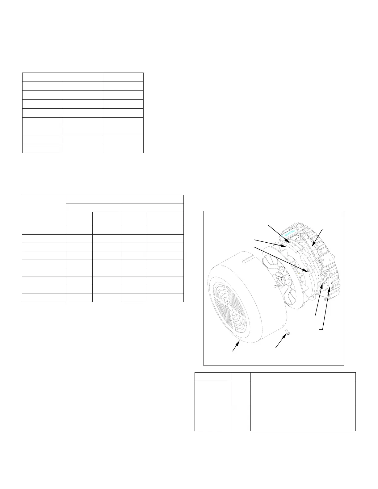
FIGURE 1:
INTEGRAL
Friction Disk
Pressure Plate
Slotted Adjustment
Screw (3)
Release Handle
Clapper Plate
Field Cup/
Motor End Shield
Fan Shroud
Screws (4)
Fan Shroud
Task: Rectifier Checks
To determine if a rectier has been damaged use a multimeter
to check resistance. Refer to internal wiring diagram, Figure 2
on page 3. Check the following lead combinations by placing
the positive clip on one lead and the negative clip on the other.
See Table 1.
Table 1
(+) (-) Resistance
B1 B4 Low
B4 B1 High
B1 B3 High
B3 B1 Low
B2 B4 Low
B4 B2 High
B2 B3 High
B3 B2 Low
If any resistance is measured low where it should be high or
vice versa, the rectier has been damaged and replacement
rectier kit (p/n 024018) should be purchased.
Table 2 Brake Coil Data: Current/Resistance Ratings
(see Table 2 notes)
Coil Voltage
Low/High
Brake Static Torque Rating
3 & 6 lb-ft 10 -50 lb-ft
Current
Draw (A)
Resistance
(8) Ohms
Current
Draw (A)
Resistance
(8) Ohms
115/230 VAC (1) 0.19 562 0.28 387
230/460 VAC (2) 0.10 2078 0.14 1550
287/575 VAC (3) 0.09 2987 0.12 2245
104/208 VAC (4) 0.24 384 0.31 290
190/380 VAC (5) 0.13 1341 0.19 923
250/500 VAC (6) 0.10 2336 0.13 1793
48VDC 0.48 100 0.58 82
24 VDC 0.97 24.7 1.14 21.7
12 VDC 1.95 6.2 2.24 5.4
Table 2 Notes: Other nameplate voltage capabilities:
1) 115/208-230 VAC 50 or 60 Hz, 133/265 VAC 60 Hz,
110-125 VDC
2) 208-230/460 VAC 50 or 60 Hz, 240/480 VAC 60 Hz,
220/440 VAC 50 Hz, 230 VDC
3) 237/575 VAC 60 Hz, 275/550 VAC 60 Hz, 300/600 VAC 60 Hz
4) 104/208 VAC 50 or 60 Hz, 100/200 VAC 60 Hz,
90-95 VDC
5) 190/380 VAC 50 or 60 Hz, 200/400 VAC 60 Hz,
208/41 6 VAC 50 Hz
6) 250/500 VAC 50 or 60 Hz
7) Values for other nameplate voltages will vary.
Consult DODGE Engineering for actual values.
8) Coil resistance is measured between leads B4 and B5.
Measured resistance may vary -7.5% from nominal values.
ELECTRICAL CONNECTIONS:
Warning:
The user is responsible for conforming with the National
Electrical Code and all other application local codes.
Wiring practices, grounding, disconnects and overcurrent
protection are of particular importance. Failure to observe
these precautions could result in severe bodily injury or
loss of life.
Caution:
Since the brake is internally wired to the motor, be sure
that the lead wires are not frayed. Failure to observe this
precaution could result in damage to or destruction of the
equipment.
Caution:
If electrical soft-start or inverter is used in the system care
must be taken to ensure that the brake is supplied with full
voltage. Brake must have the full input voltage to ensure
proper release and operation.
Caution:
Replacement/Retrofit Applications: To ensure proper
wiring connections when placing this brake in place of
another, be sure to trace motor leads back to the motor
conduit box. Brake lead markings may differ among brake
manufacturers. If in doubt, voltages should be measured.
Refer to Table 3 for standard brake connections for separately
connected Short Series brakes.
Figure 1
Table 3 Standard Brake Connections
Motor Volts Connect
Separately
Connected
Brake
Low B1 -L1
B2-L2
B3 & B5 -Insulate
B4 -Insulate
High
B1 & B5 -L1
B3 -Insulate
B4 -Insulate
B2-L2
Notes:
1) Check compatibility of motor and brake voltages with power supply.
2) Insulate means: tie together (or alone) and cap off and insulate.
3) B1 to B5 are Brake lead connections. L1 & L2 are AC Power connections.
 Loading...